
An internal groove can make a copper tube more effective at exchanging heat with the fluid inside it. That does not mean a grooved replacement will increase the capacity of an existing coil by the same percentage. Tube-side performance is one part of a larger thermal and hydraulic system.
The useful question is where the improvement occurs, what operating conditions produce it, and whether another resistance limits the final result. This article examines the inside surface; the copper heat exchanger overview places enhanced tubing within the wider equipment choices.
Executive Summary
- Grooves change internal surface area and fluid behavior; they do not change copper into a material with a higher intrinsic conductivity.
- A heat-transfer coefficient is meaningful only with its reference area and test conditions.
- Compare heat duty and pressure loss together, then check the complete coil at the intended operating point.
- Preserve the specified internal profile during fabrication; outside diameter alone cannot identify an equivalent tube.
How the Internal Surface Changes Heat Transfer
More surface, different near-wall flow
Smooth tubing presents a comparatively simple inside surface. Engineered internal ridges add surface and influence fluid movement close to the wall. CDA describes their role in increasing internal heat-transfer coefficients and disrupting boundary-layer development. The result depends on the profile and the actual flow regime.
In a refrigeration application, the surface can interact with a changing liquid-vapor mixture. A result obtained during evaporation should therefore not automatically be used for condensation, and a result for one refrigerant or mass flow should not be treated as universal. The condenser and evaporator comparison explains those different duties. Request data covering the intended duty. For a practical example of this internal surface design, see Nexnice’s Micro-fin Inner Grooved Copper Tube (IGT) for available groove geometry specifications and HVAC applications.
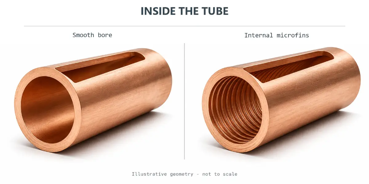
Conductivity and convection are different
Copper conducts heat through the tube wall. Grooving primarily changes the boundary between that wall and the internal fluid. Keeping these effects separate prevents a misleading explanation that grooves simply make copper “conduct heat faster.” A useful performance report describes both the geometry and the fluid-side conditions.
Read a Performance Claim Before Accepting It
Identify the reference area
Heat-transfer conductance is commonly expressed as a coefficient multiplied by its reference area. An enhanced surface has more actual internal area than a smooth cylinder with a comparable nominal diameter. If two reports use different area conventions, comparing their coefficient values directly may be misleading.
Ask whether the reported coefficient uses actual developed internal area, a nominal smooth-bore area, or an outside-area basis. Keep the same convention when calculating overall conductance. Counting the added area once in the coefficient definition and again as an extra multiplier would exaggerate the predicted benefit.
Hold the comparison conditions steady
“Same diameter” is an incomplete comparison. Record refrigerant, phase condition, mass flow, inlet state, active length and pressure drop. At the coil level, also record airflow, fin arrangement and circuit count. A tube comparison and a redesigned-coil comparison answer different questions and should be reported separately.
| Comparison question | Keep visible | Useful result |
|---|---|---|
| Does the internal profile help at this flow? | Area convention and fluid state | Heat transfer with measured pressure loss |
| Can the coil become smaller? | Required duty and operating envelope | Validated dimensions at equal duty |
| Does system efficiency improve? | Fan, compressor, and operating conditions | Complete-system energy result |
No single coefficient establishes all three outcomes. A manufacturer may legitimately redesign the entire coil, but the resulting system improvement should not be attributed solely to one groove dimension.
Why a Strong Tube-Side Result May Give a Modest Gain
The largest resistance still matters
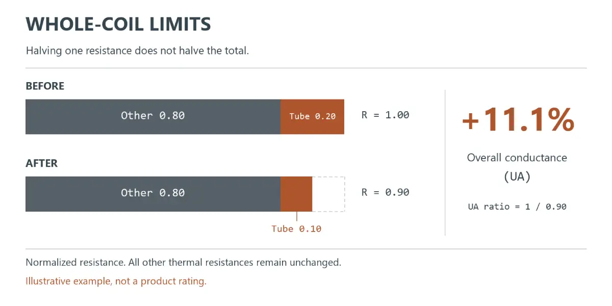
Consider a deliberately simplified resistance model. Suppose the tube-side contribution is 20% of the total thermal resistance, with all other contributions making up 80%. If a design change halves only that tube-side contribution, total resistance becomes 90% of the original. At unchanged driving temperature difference, conductance rises by about 11%, not 100%.
This is an illustrative calculation, not a typical coil rating. It explains why improving one part of the heat path cannot bypass the remaining resistances. For an air-cooled coil, fins, tube-to-fin contact and airflow deserve attention alongside the internal surface.
Evaluate the pressure-loss tradeoff
A thermal gain is incomplete without its hydraulic consequence. Compare the flow condition the system will actually deliver, not at a convenient laboratory flow that requires a different pumping or compression duty. If circuit layout changes, recalculate distribution and pressure losses rather than keeping the original prediction.
The acceptance criterion should say what must improve: capacity within the same envelope, a smaller envelope at the same capacity, or lower energy at specified conditions. Those are different objectives and can lead to different profiles.
Specify the Profile as a Manufactured Feature
Use an unambiguous cross-section
Request a cross-sectional drawing identifying the outside diameter, minimum remaining wall convention and the internal ridge profile. Where the design uses groove count, helix angle or ridge height, show the measurement definitions. Do not let two suppliers interpret “wall thickness” differently for the same enhanced section.
Rather than inventing a universal tolerance, agree on the profile limits and how the finished tube will be checked. Include a reference image or section definition if a dimensional label could be interpreted in more than one way.
Check the condition after assembly
The relevant surface is the one inside the completed exchanger. A development plan should examine whether forming and assembly leave the intended profile intact at critical locations. This is an inspection recommendation, not a claim that a particular expansion process always damages grooves.
When discussing a profile with Nexnice, provide the reference drawing and the condition in which acceptance is required. An incoming tube cross-section and a completed coil test serve different purposes; keep both results identifiable.
Conclusion
Inner-grooved tubing is most useful when its internal improvement addresses a meaningful part of the exchanger’s thermal resistance. Specify the profile, compare like operating conditions, and judge the result against the complete coil objective. A credible evaluation explains the mechanism and the limits without promising a universal percentage gain.
Frequently Asked Questions
Do grooves increase copper’s thermal conductivity?
No. Their main purpose is to change the internal surface and its interaction with the fluid. Copper’s material conductivity and the fluid-side heat-transfer coefficient are different properties. A clear technical comparison should distinguish them and identify the operating conditions.
Is a higher coefficient always a better result?
Not by itself. Check the reference area, pressure loss and operating state behind the coefficient. Then determine whether the resulting conductance improves the complete exchanger at the required duty without unacceptable changes elsewhere in the system.
Can evaporation data predict condensation performance?
It should not be transferred automatically. The phase behavior and liquid distribution differ between those duties. Use data or a validated model applicable to the intended refrigerant, flow and operating state, then confirm the assembled coil’s performance.
Why must the area basis be stated?
A coefficient depends on the area used in its definition. Comparing an actual enhanced-area value with a nominal smooth-area value can distort the apparent improvement. Keep the coefficient and its area convention paired throughout the calculation and comparison.
Is outside diameter enough to order equivalent grooved tubing?
No. Tubes with the same outside diameter can have different remaining wall and internal profiles. Define the relevant cross-section, material condition and acceptance method. Equivalence also requires evidence that the intended operating performance and manufacturing requirements remain satisfied.
Discuss an Enhanced Tube Profile
Send Nexnice your cross-section and the performance comparison conditions through the tube profile inquiry form. Identify whether your objective is compactness, capacity or energy reduction so the technical discussion has a measurable purpose.