
Inner grooved copper tube has ridges or microfins formed on the inside wall. The profile changes the fluid’s contact with the wall and can increase developed area. It does not create a new alloy, erase pressure-drop limits, or guarantee a fixed capacity gain. Designers need a cross-section and an operating condition before evaluating the tube.
The useful starting point is the cross-section: which dimensions describe the pressure boundary, which describe the internal surface, and which must survive fabrication? Those dimensions also establish the starting point for a comparison with smooth copper tube.
Executive Summary
- Groove geometry includes more than the outside diameter and nominal wall.
- The profile primarily changes the tube-side fluid interaction and available area.
- Evaporation, condensation, and single-phase flow may respond differently.
- Forming, expansion, circuit distribution, and pressure drop must be reviewed with the thermal result.
Read the Cross-Section
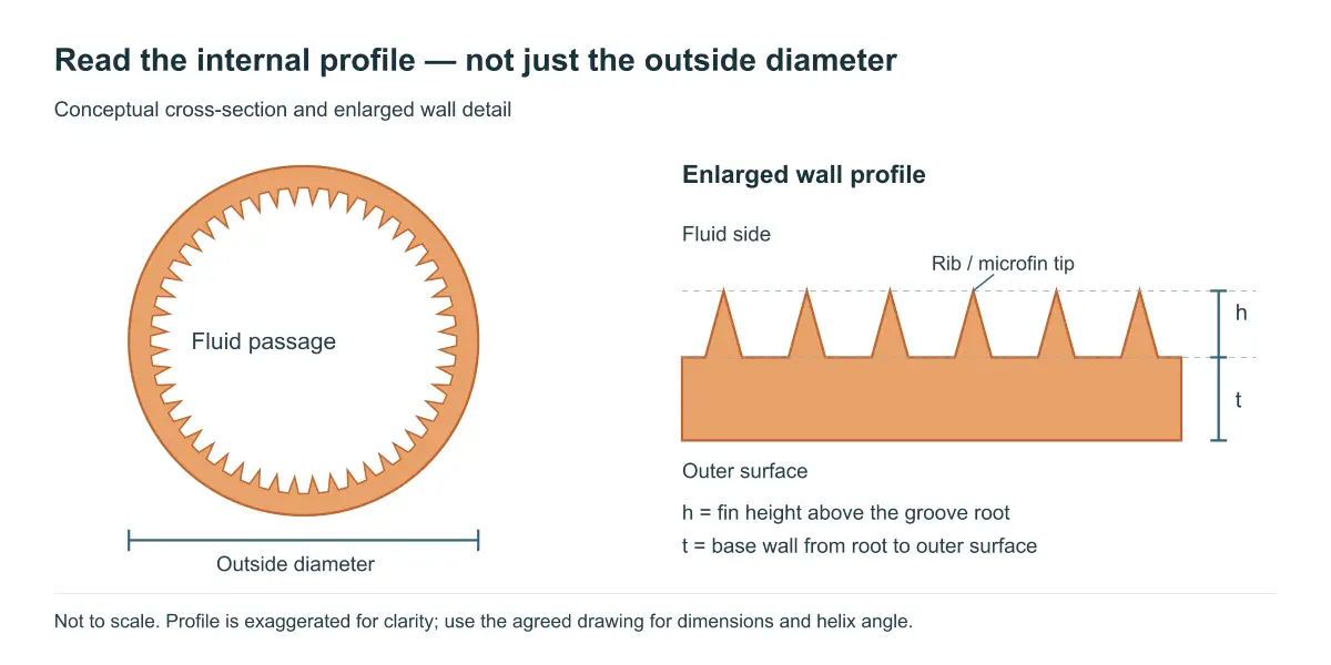
Separate top, base, and groove dimensions
A drawing should identify outside diameter, inside reference, base-wall thickness, groove height or depth, helix angle, number of starts, and dimensional tolerances. The measurement convention matters because a developed internal area is different from a smooth-bore nominal area. Nexnice’s micro-fin copper tube specifications identify fin height, helix angle, bottom wall, and outside diameter as separate fields. Use those distinctions when reading a profile; the drawing should define the agreed dimensions and measurement locations.
Preserve the remaining wall
The ribs and channels are part of the tube profile, so the distance from the groove root to the outside surface remains part of the mechanical design. A high-looking fin can be unacceptable if it leaves an inadequate base wall for forming or service. Do not convert a profile drawing into a pressure rating without the applicable design basis.
Why the Profile Changes Heat Transfer
More contact area
A grooved surface can expose more internal area to the fluid than a smooth cylinder with the same nominal OD. Report each heat-transfer coefficient with the reference area used to calculate it. If a coefficient is based on a nominal smooth-cylinder area, use that same area when calculating hA; do not multiply it by the larger developed surface area without converting the coefficient. If the coefficient is based on the actual grooved surface, use that developed area.
Different near-wall flow
Ridges disturb the fluid close to the wall and may promote mixing or redistribute liquid. The response depends on mass flux, vapor quality, refrigerant properties, orientation, and groove geometry. A profile that helps one regime should not be described as universally better across evaporation, condensation, and single-phase service.
Where HVAC Designers Use It
Refrigerant-to-air coils
Small-diameter internally enhanced tubes can be used in evaporator or condenser circuits. The airside fin contact, circuit length, headers, and refrigerant distribution remain part of the design. A tube-only test cannot establish a finished coil’s capacity.
Compact heat exchangers
When the available face area or refrigerant charge is constrained, the designer may evaluate a smaller tube or a higher internal area. The objective can be a smaller envelope, a lower charge, or a different circuit arrangement. State the objective before selecting a profile so that pressure loss and manufacturing complexity are visible.
Single-phase and process duties
Water or other single-phase flows require their own velocity, fouling, chemistry, and cleaning review. Do not copy refrigeration evidence into a water application without checking the fluid and boundary conditions.
Two Questions That Need Different Evidence
Is it preferable to a smooth tube?
An equal outside diameter makes two tubes look interchangeable but does not establish equal flow area or thermal behavior. Compare the options at a defined duty and pressure-drop limit, using the same area convention for the reported heat-transfer coefficients. Equal dimensions alone do not establish an equivalent replacement.
Will it improve equipment efficiency?
Reducing internal resistance can improve heat transfer, but the airside, fin contact, and other parts of the exchanger remain in the heat path. A local coefficient gain therefore need not become an equal capacity gain, and capacity alone does not establish energy savings. The heat exchanger efficiency analysis explains those separate steps.
Compare the Whole Design
| Question | Evidence needed | What it prevents |
|---|---|---|
| What geometry is supplied? | Cross-section and profile limits | OD-only substitution |
| What duty is required? | Fluid state, flow, temperatures | Coefficient-only claims |
| What hydraulic limit applies? | Pressure-drop calculation or test | Unaccounted tube-side pressure loss |
| Does the post-forming profile meet the specified limits? | Post-forming inspection | Damaged internal ribs |
| Does the complete coil meet duty? | Assembled test at stated conditions | Tube test overclaim |
Manufacturing and Acceptance
Forming may affect groove height, helix, wall, and ovality. For mechanical expansion, include a post-expansion profile check to establish whether the intended geometry has been retained. Define the sample plan, cross-section method, end preparation, cleanliness, and any leak or pressure test separately. Keep the incoming tube record connected to the finished coil record.
Conclusion
Inner grooves are an engineered internal surface, not a separate copper grade or a universal performance rating. Read the profile drawing, establish the intended flow regime, and distinguish incoming geometry from the finished assembly. That provides a useful starting point for a smooth-tube comparison or a system-efficiency assessment without assuming either result in advance.
Frequently Asked Questions
What is an inner grooved copper tube?
It is copper tubing with an engineered internal rib or microfin profile. The grooves alter the fluid-side surface and flow path. The final specification still needs alloy, OD, base wall, profile dimensions, tolerances, temper, cleanliness, and the operating conditions used to judge performance.
Does a groove increase copper conductivity?
No. Copper’s material conductivity is separate from the fluid-side effect of the internal profile. A groove can change area and near-wall flow, while wall conduction remains governed by the material and remaining wall. Thermal models should keep those contributions distinct.
Is the groove visible from outside?
Usually the external appearance does not identify the internal profile. Tubes with similar outside diameters can have different groove counts, heights, helix angles, and base walls. Use a controlled drawing or cross-section rather than a photograph to establish the product.
Can an inner grooved tube replace a smooth tube directly?
Not without review. Check refrigerant or fluid conditions, pressure drop, wall and profile, forming route, headers, circuit distribution, and the assembled coil test. An equal outside diameter does not demonstrate equal hydraulic or thermal behavior.
Which documents should a buyer request?
Request the profile drawing, dimensional and material specification, cleanliness and end condition, forming guidance, inspection method, and test conditions. If a performance comparison is supplied, ask for the area basis, fluid state, mass flow, active length, and pressure-drop result.
Request a Technical Review
Contact Nexnice with the cross-section, fluid conditions, required duty, pressure-drop limit, forming route, and inspection plan. The profile can then be considered within the complete HVAC heat-exchanger design.