
A smooth copper tube and an inner grooved tube can share the same outside diameter while presenting different internal geometry. That difference affects developed area, near-wall flow, hydraulic resistance, forming, and inspection. A fair comparison therefore starts by fixing the question and the operating conditions.
The inner-grooved tube overview defines the geometry. This page focuses on how to compare two alternatives without turning one coefficient, photograph, or catalog sentence into a whole-coil conclusion.
Executive Summary
- Define which conditions are fixed and which design variables may change; report thermal performance and pressure drop together.
- Report the coefficient together with its reference area and test condition.
- Check base wall, forming, expansion, circuit distribution, and airside resistance.
- Choose the tube whose complete assembly meets the required duty and operating envelope.
Define the Comparison Before Testing
Choose the accepted output
A comparison can ask whether capacity rises at the same envelope, whether the envelope shrinks at the same duty, or whether energy use falls at a defined operating point. Those are different objectives. Write the objective before selecting the tube so the test does not reward an irrelevant variable.
For an OEM candidate, the inner-grooved copper tube product page from Nexnice lists the drawing and order inputs used to identify the tube. Match that proposed cross-section to the smooth-tube reference before requesting a performance comparison.
Hold the refrigerant state steady
For two-phase work, state pressure, temperature reference, quality or superheat/subcooling convention, mass flow, and orientation. A result from evaporation cannot be transferred to condensation without a reason. For single-phase work, state fluid properties, inlet temperature, velocity, and fouling assumption.
Understand What the Numbers Mean
Coefficient and area are paired
A heat-transfer coefficient is meaningful only with the area used to define it. Developed grooved area, nominal smooth-bore area, and outside area can produce different numerical coefficients. Record the coefficient, reference-area definition and value, and active length together. Identify whether the reported conductance is tube-side hA or overall exchanger UA; they represent different parts of the heat-transfer path.
Pressure drop is part of performance
The profile may improve tube-side convection while increasing friction. That extra pressure loss can change compressor or pump work and can affect distribution across parallel circuits. A thermal comparison without pressure drop leaves a material system consequence unreported.
Compare Fabrication and Reliability
Check base wall and expansion
Internal fins must survive bending, brazing, and mechanical expansion. The comparison should include the remaining base wall and the post-forming cross-section. Do not assume the qualified expansion tooling for one profile is suitable for the other; check the completed coil.
Check circuit distribution
A tube profile does not correct a poorly designed header. Compare circuit length, header pressure balance, refrigerant distribution, fin contact, and airside condition. If those variables change between prototypes, attribute the result to the complete design rather than to the groove alone.
Fair Comparison Table
| Comparison item | Smooth tube record | Grooved tube record |
|---|---|---|
| Geometry | OD, wall, bore | OD, base wall, profile |
| Thermal basis | Reference-area definition and value; corresponding coefficient; tube-side hA or overall UA, clearly identified | Reference-area definition and value; corresponding coefficient; tube-side hA or overall UA, clearly identified |
| Hydraulic basis | Flow and pressure drop | Flow and pressure drop |
| Assembly | Forming and expansion record | Forming and expansion record |
| Final result | Coil duty at stated conditions | Coil duty at stated conditions |
A Hypothetical Area-Basis Check
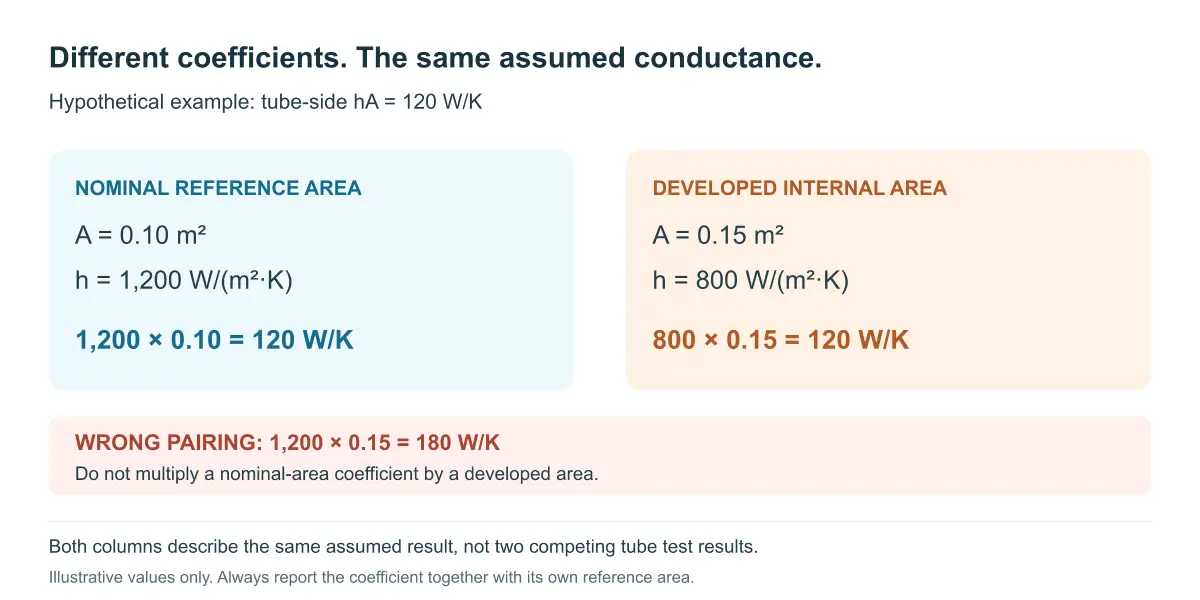
For this hypothetical calculation, assume a tube-side conductance hA of 120 W/K. Suppose the nominal reference area is 0.10 m² and the developed internal area is 0.15 m². Expressed in nominal area, h is 120 / 0.10 = 1,200 W/(m²·K). Expressed on the developed area, h is 120 / 0.15 = 800 W/(m²·K). These are two descriptions of the same assumed result, not evidence that one tube transfers more heat.
Multiplying the nominal-area coefficient by the developed area would incorrectly report 180 W/K. Keep each coefficient paired with its own area. The example isolates a reporting error; it does not predict a real groove’s area or coefficient. For the separate question of how a tube-side change propagates through an exchanger, see the whole-coil efficiency explanation.
Decide Whether the Advantage Is Meaningful
Separate controlled tests from redesigns
In a tube-only comparison, hold the surrounding design constant as far as practical and disclose unavoidable differences. In an optimized-design comparison, each option may have a different circuit count or tube length. Both tests can be useful, but the second establishes which design performs better, not the isolated effect of adding grooves.
Include uncertainty and off-design operation
Request instrument uncertainty, heat-balance closure, and repeated measurements. A small difference that falls within the test uncertainty is not a demonstrated improvement. Check representative low and high loads as well as the nominal point; one favorable operating point does not establish the better choice over the equipment’s full duty range.
Conclusion
A fair comparison keeps the design objective visible and the measurement basis consistent. Compare conductance rather than unmatched coefficients, report pressure loss alongside thermal performance, and separate a tube-only experiment from a redesigned coil. The preferred option is the one that meets the stated objective across the operating range, with an advantage larger than the measurement uncertainty.
Frequently Asked Questions
Is grooved tube always better than smooth tube?
No. Grooved tubes can improve a tube-side contribution under suitable conditions, but pressure drop, airside resistance, distribution, cost, and forming can change the whole result. Compare both tubes at the same duty, fluid state, active length, and acceptance criteria.
Should the outside diameter be the same?
That depends on the design question. Equal outside diameter can isolate an internal-profile change, but it does not make the tubes equivalent. The comparison still needs base wall, bore, profile, pressure drop, forming limits, and the assembled coil conditions.
Why state the area basis?
The area basis determines the reported coefficient. A developed grooved area can be larger than a smooth nominal area, so comparing coefficients from different conventions can create a false advantage. Report area, coefficient, length, and total conductance together.
Can a grooved tube use the same headers?
Possibly, but the answer requires a circuit and connection review. Check tube OD, insertion depth, joint method, header distribution, allowable pressure loss, and post-braze condition. Similar outside dimensions do not remove the need to validate the complete assembly.
What should an RFQ request for a comparison?
Request both cross-sections, material and wall definitions, fluid and test conditions, active length, flow, pressure-drop limit, area convention, forming route, and inspection evidence. Ask the supplier to identify assumptions and deviations instead of presenting one headline coefficient.
Request a Technical Review
Contact Nexnice with the two candidate drawings, operating conditions, duty, pressure-drop limit, and planned forming process. A comparison can then be made on the same basis and tied to the finished coil.