
A copper coil heat exchanger turns a length of tube into a usable heat-transfer surface inside a limited space. The difficult part is deciding how that length should be arranged. Ten metres of tightly packed tubing and ten metres spread through an effective flow path do not necessarily provide the same duty.
Start by identifying what surrounds the coil. Air, a flowing liquid inside a shell and a relatively still tank create different design problems. The heat exchanger configuration overview puts those arrangements in context; this article follows the coil from its drawing geometry to a buildable component.
Executive Summary
- Distinguish a formed heat-transfer coil from coiled tubing supplied as raw material.
- Specify tube diameter, coil centreline diameter, pitch, turns and connection positions separately.
- Calculate developed tube length before estimating bare-tube surface area.
- Review the fluid path around the coil and the distribution between parallel circuits.
- Include installation and removal clearances in the finished envelope.
Which Coil Arrangement Fits the Space?
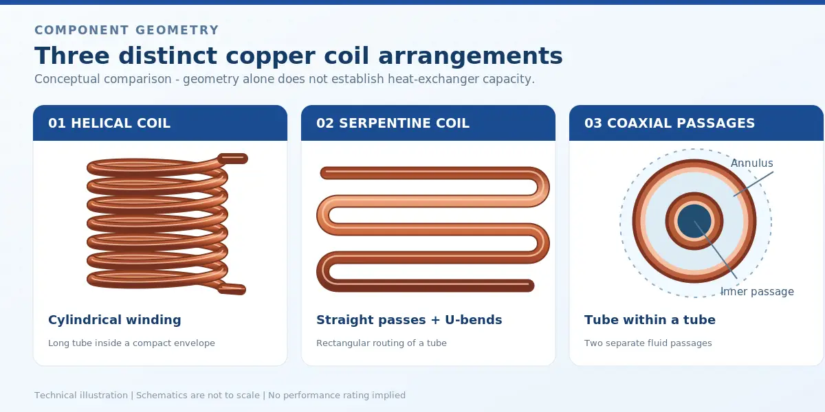
Helical coils
A helix wraps around an axis and advances with each turn. It can package a long tube within a cylindrical envelope. ASHRAE describes shell-and-coil exchangers using this arrangement, with spacing between tube layers. The practical design question is how the surrounding fluid reaches the surface rather than bypassing the bundle.
Show the shell, baffles or flow guides on the assembly drawing. A drawing of the copper alone cannot establish the external flow path. If the coil is submerged in storage water instead, the immersion coil application guide addresses tank circulation and changing water temperature.
Serpentine and finned coils
A serpentine layout uses repeated straight passes and return bends. It suits a rectangular face and can be combined with fins for air service. The return bends and headers occupy space outside the active face, so distinguish the heat-transfer face from the full installation envelope.
For an air coil, also show airflow direction and access to the face. A narrow enclosure that blocks part of the face defeats an otherwise sensible tube layout. Fin selection and tube-to-fin contact belong in the complete coil rating, not in a bare-tube area calculation.
Coaxial coils
In a coaxial exchanger, an inner tube sits within an outer tube, providing two separate flow passages. Coiling the pair can make the package compact, but the annular passage still needs defined inlet and outlet connections. A copper tube rolled into a helix without a second passage is not automatically a coaxial heat exchanger.
| Layout | Useful geometric feature | Detail the drawing must resolve |
|---|---|---|
| Helical | Cylindrical arrangement with repeated turns | Pitch, layers and surrounding flow path |
| Serpentine | Rectangular active face | Return-bend clearance and pass connections |
| Coaxial | Two fluids inside concentric passages | Annular connections and complete circuit routing |
Calculate Length From the Centreline
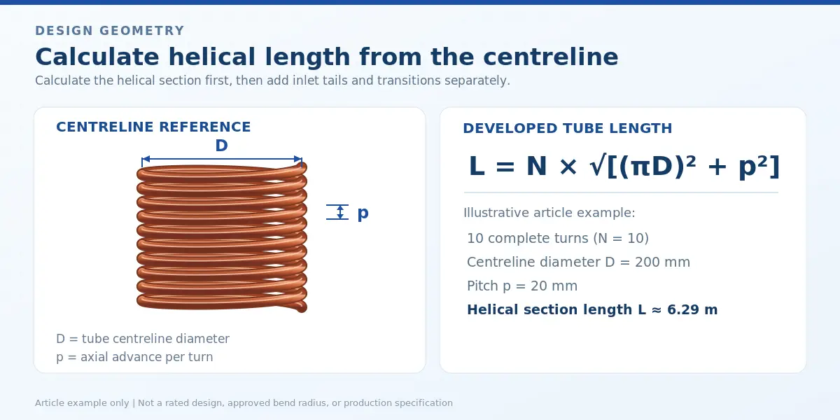
For an ideal constant-pitch helix, the developed length is:
L = N × √[(πD)² + p²]
Here, N is the number of full turns, D is the coil centerline diameter, and p is the axial advance per turn. Use the same length unit for D and p. Add inlet and outlet tails, transitions and any other formed sections separately.
Consider an illustrative 10-turn helix with a 200 mm centreline diameter and a 20 mm pitch. The helical section is approximately 6.29 m long. With 10 mm OD bare tube, its nominal external surface is π × 0.010 × 6.29, or about 0.198 m². These are geometric results; they do not establish capacity, an approved bend radius or a pressure rating.
Do not substitute the coil’s outside diameter into the centreline formula without adjustment. Similarly, define the axial envelope on the drawing rather than assuming “turns times pitch” includes tube thickness and end details.
Area Alone Does Not Determine Capacity
Leave a usable path around the turns
Reducing pitch fits more turns into a fixed height, but also changes the passage available to the external fluid. Review spacing with the intended flow direction, debris exposure and cleaning method. “Maximum turns” is a packaging objective, not a thermal acceptance criterion.
Evaluate the assembled geometry at the intended operating conditions. Request the external flow assumptions used in the rating, especially where a shell or enclosure allows fluid to pass around rather than through the active region.
Decide where circuits divide
One long tube has a simple connection arrangement. Several parallel paths introduce headers and a distribution question. Specify the number of circuits, their lengths and how the headers connect them; a total tube length cannot describe that network.
When reviewing alternatives, keep total flow and external conditions fixed. Ask how each option divides the flow and how the predicted pressure loss includes bends and headers. This makes the choice reviewable without assuming that adding parallel paths automatically produces the required duty.
Release a Drawing the Fabricator Can Measure
Define reference faces and connection datums. For a helical coil, list centreline diameter, pitch, turn count, handedness where relevant, tail lengths and the angular relationship between the connections. For a serpentine coil, show straight-pass length, pass spacing, bend geometry and inlet/outlet orientation.
Then identify critical finished-part measurements. We recommend checking a first article in a fixture representing the mounting arrangement, followed by dimensional inspection at the most demanding bend. Specify acceptable deformation through engineering review rather than assuming that any visibly round coil is satisfactory.
Installation clearances deserve equal attention. The coil may fit inside the operating space yet fail to pass through the access opening. Show the insertion direction and the route used to remove it for service. Avoid locating a permanent joint where the intended inspection method cannot reach it.
Approve the Assembly, Not Just the Wound Shape
A practical review package combines the geometry drawing, circuit schematic and required performance conditions. Keep the material specification separate from geometric tolerances so a change to the tube does not silently change the accepted shape.
For a Nexnice discussion, an annotated sketch of the surrounding shell or enclosure is more informative than a photograph of a similar coil. It lets the inquiry distinguish the copper component from the complete exchanger whose performance must be established.
Conclusion
A useful coil design connects developed length, flow routing and assembly space. Check all three before selecting a winding geometry. A well-defined coil drawing should explain where the tube goes, how the fluids reach it and how the finished part can be installed and inspected.
Frequently Asked Questions
Is a pancake coil already a heat exchanger?
Not necessarily. “Pancake coil” can describe tubing packaged for supply rather than a rated exchanger. Establish the intended fluid paths, mounting geometry and thermal conditions before treating a coil of raw tubing as a finished heat-transfer component.
Which diameter belongs in the helix length formula?
Use the diameter measured to the tube centreline. The coil outside diameter includes the tube itself and gives a different developed length. Define the measurement convention on the drawing and add connection tails and transitions separately to the calculated helical length.
Will additional turns always increase useful output?
No. Additional turns add nominal surface but also change length, spacing and fluid routing. Their value depends on whether the surrounding fluid reaches that surface and whether the circuit remains within its permitted pressure loss and assembly envelope.
Can one coil drawing describe several circuits?
Yes, provided the drawing includes an unambiguous circuit schematic. Total tube length and external dimensions do not identify which passes connect. Show headers, flow directions and the number of paths so manufacturing and rating use the same arrangement.
How should coil fit be verified before production?
Verify a first article against the installation datums and the actual insertion path. Check connection positions, envelope and critical bends with suitable fixtures or measurement methods. A visual comparison with a sample photograph does not establish dimensional interchangeability.