
A mini split-line set size chart is useful for identifying a pipe pair. It becomes misleading when the same chart assigns that pair to every unit of a particular capacity. The required sizes come from the specified indoor and outdoor equipment combination, not from a universal BTU rule.
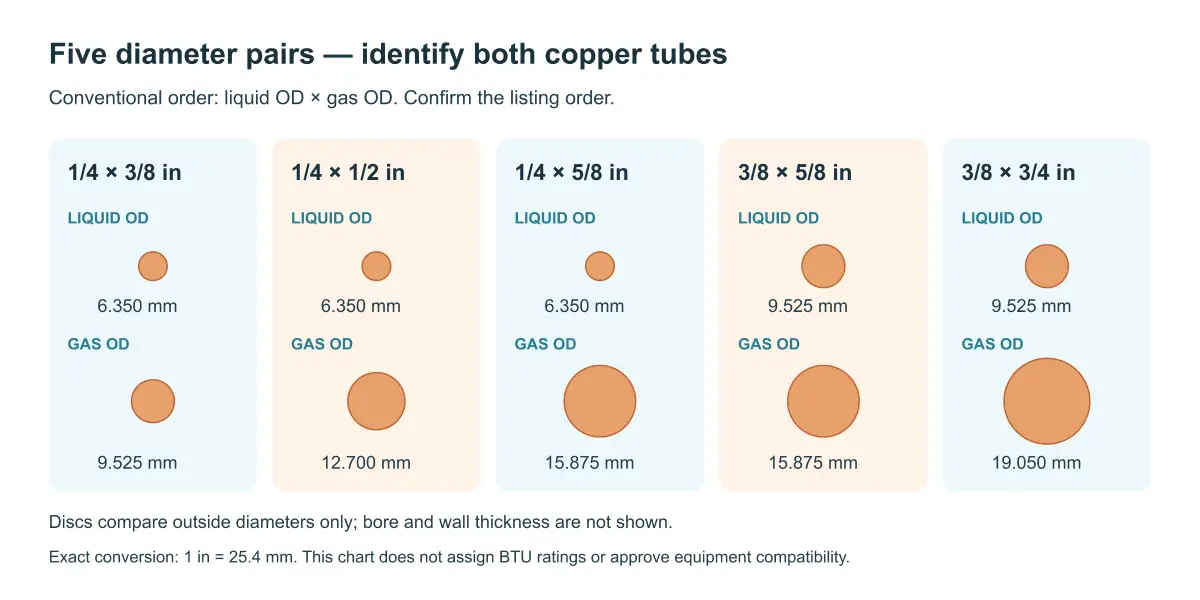
The five pairs below compare actual copper outside diameters. Use them to translate a manufacturer’s requirement into a clear line-set description, then check the connections and remaining tube specifications. None of the rows independently approves a line set for a particular system.
Executive Summary
- Read both numbers as copper outside diameters, usually listed as a liquid line followed by a gas line.
- Keep copper diameter, wall thickness, insulation thickness, and coupling size in separate fields.
- Match the full equipment model; similar capacity descriptions can require different gas-line diameters.
- Treat a reducer or adapter as a proposed design detail requiring approval, not automatic compatibility.
- Confirm diameter first, then review length, elevation, and installation requirements separately.
Mini Split Line Set Size Chart
Five pairs, with exact inch-to-millimeter conversions
The table assumes the conventional liquid-line × gas-line order. Confirm that order in the equipment schedule and supplier listing. The metric figures are arithmetic conversions using 25.4 mm per inch; they do not specify manufacturing tolerances or authorize substitution with a nearby metric tube size.
| Pair designation | Liquid OD | Gas OD | What to confirm |
|---|---|---|---|
| 1/4 × 3/8 in | 6.350 mm | 9.525 mm | Both ports and the specified refrigerant tubing requirements |
| 1/4 × 1/2 in | 6.350 mm | 12.700 mm | The larger gas line is required for the selected model |
| 1/4 × 5/8 in | 6.350 mm | 15.875 mm | A 1/4 in liquid line remains specified with this gas line |
| 3/8 × 5/8 in | 9.525 mm | 15.875 mm | Both sizes are expressly listed; do not infer approval from one matching port |
| 3/8 × 3/4 in | 9.525 mm | 19.050 mm | The equipment requires this complete pair and matching connections |
A catalog may round these diameters to 6.35, 9.52, 12.7, 15.88 or 19.05 mm. Keep the governing inch designation or exact metric specification in the order. A rounded display value helps recognition, but it is not a substitute for the manufacturer’s dimensional requirements.
For the rest of the assembly decisions, the mini split line set guide connects diameter selection with insulation and connection type. Once the pair is settled, the installed line set length guide addresses route and charge limits without changing the meaning of this size chart.
Read a pair as two independent requirements
Changing from 1/4 × 3/8 to 1/4 × 1/2 leaves the smaller tube unchanged and changes the larger tube. Changing from 1/4 × 5/8 to 3/8 × 5/8 does the opposite. These are distinct assemblies even when one leg looks identical.
That distinction matters when stock is labeled informally as “the 5/8 set.” Such a description does not say whether the other tube is 1/4 or 3/8 inch. Identify both sizes on the package and the job schedule before the installer opens the coil.
How the Five Pairs Differ in Practice
1/4 × 3/8 inch
This pair combines the smallest two copper diameters in the comparison. The reviewed Daikin RXM09WVJU9/RXM12WVJU9 manual specifies a 1/4 inch liquid pipe and 3/8 inch gas pipe for its listed systems. That is a model-specific example of the pair, not a rule covering every small-capacity mini split.
When replacing a supplied assembly, check whether the specified ends are conventional flares or proprietary connectors. The same bare copper diameters do not make those two end arrangements interchangeable. Retain the required tube wall and material specification too; the pair label does not contain either value.
1/4 × 1/2 inch
Pioneer’s model lookup lists a 1/4 inch liquid line and 1/2 inch gas line for WYT018GLSI24RL. The practical difference from the preceding row is the gas pipe. A stock item with a 3/8 inch gas line does not become the specified assembly merely because its liquid line fits.
If a quotation substitutes this pair for another, have the change identified explicitly. A general note such as “suitable for 18,000 BTU” is not enough to resolve the substitution. The complete model requirement should be attached to the item description.
1/4 × 5/8 inch
The same Pioneer lookup lists WYT036GLUI17RL with a 1/4 inch liquid line and 5/8 inch gas line. It illustrates why the larger tube should not be used to guess the smaller one. A 5/8 inch gas-line requirement does not automatically imply a 3/8 inch liquid line.
The larger insulated leg can also affect the physical space required through a wall or inside a cover. Check the finished assembly dimensions when planning that space. Bare tube OD is the connection reference; it is not the complete installation envelope.
3/8 × 5/8 inch
This pair shares its larger tube with the previous row and its smaller tube with the next row. It therefore deserves a complete two-number label. Neither neighboring pair is an equivalent substitution.
The primary equipment examples selected for this article do not establish a model application for this pair. Include it in the dimensional comparison, but require an explicit equipment schedule before assigning it to a job. Leaving an application unassigned is more useful than inventing a capacity range to fill a chart.
3/8 × 3/4 inch
Pioneer’s lookup lists CYB036GMSI20RL and CYB048GMSI20RL with a 3/8 inch liquid line and 3/4 inch gas line. These named examples show that a larger pair can be specified for particular equipment; they do not extend the same requirements to every system carrying a similar capacity label.
Keep the indoor-unit identification connected to its approved outdoor combination. In a system with branches or connection adapters, the pipe required along the route may need additional documentation. A visible service-port size alone may not describe the entire approved piping arrangement.
Why Capacity Alone Cannot Select the Pair
Compare the model suffix, not just the number
Pioneer’s lookup provides a useful counterexample to universal sizing. It lists WYT018GLUI17RL with 1/4 × 3/8 inch piping and WYT018GLSI24RL with 1/4 × 1/2 inch piping. Both model codes contain “018,” yet their listed gas pipes differ.
The lesson is narrow and practical: retain the complete model code when looking up the required diameter. A shortened description can conceal the product-family difference that determines the correct pair. Do not extend either model’s entry to all units described as 18,000 BTU.
If a general help page and the installation manual supplied with the equipment disagree, pause the affected selection and obtain clarification for that exact revision. Do not settle the discrepancy by choosing the larger pipe or the size most readily available in the warehouse.
A fitting adapter does not redesign the circuit
An adapter may allow two different connection sizes to meet physically. That does not prove the proposed tubing diameter is acceptable over the installed route. Approved adapters belong to a specific piping arrangement and should be used under its instructions.
For a hypothetical stock substitution, suppose the job schedule requires 1/4 × 1/2 inch, but the available coil is 1/4 × 3/8 inch. The smaller leg matches; the larger leg does not. Adding a fitting at the end addresses the connection shape only. Acceptance still requires equipment-manufacturer approval of the changed pipe arrangement.
This example does not predict a particular efficiency loss or failure. Its purpose is to distinguish geometric connection from documented compatibility. Without the relevant design information, an invented performance percentage would add false precision.
Dimensions That Must Stay Separate
Copper OD and bore
Outside diameter measures the copper tube across its outer surface. The bore depends on wall thickness as well. Two tubes with the same OD can therefore have different internal dimensions if their walls differ.
Do not obtain the copper OD by measuring the outside of the insulation. Where dimensional inspection is required, use an appropriate accessible bare-tube location without damaging a prepared flare or removing protected ends unnecessarily. Follow the agreed inspection method and the specified tolerances.
Nor should a plumbing nominal-size label be substituted for an ACR tube OD designation without checking the actual dimensions. Use the equipment’s piping terminology consistently through the schedule, quotation, and package label. Familiar fractions can refer to different dimensional conventions in different product categories.
Insulation ID and thickness
Insulation inside diameter must fit the tube, while its wall thickness provides part of the thermal design. Neither is the same as the tube’s copper wall. A listing that says “3/8 insulation” needs clarification about which dimension it describes.
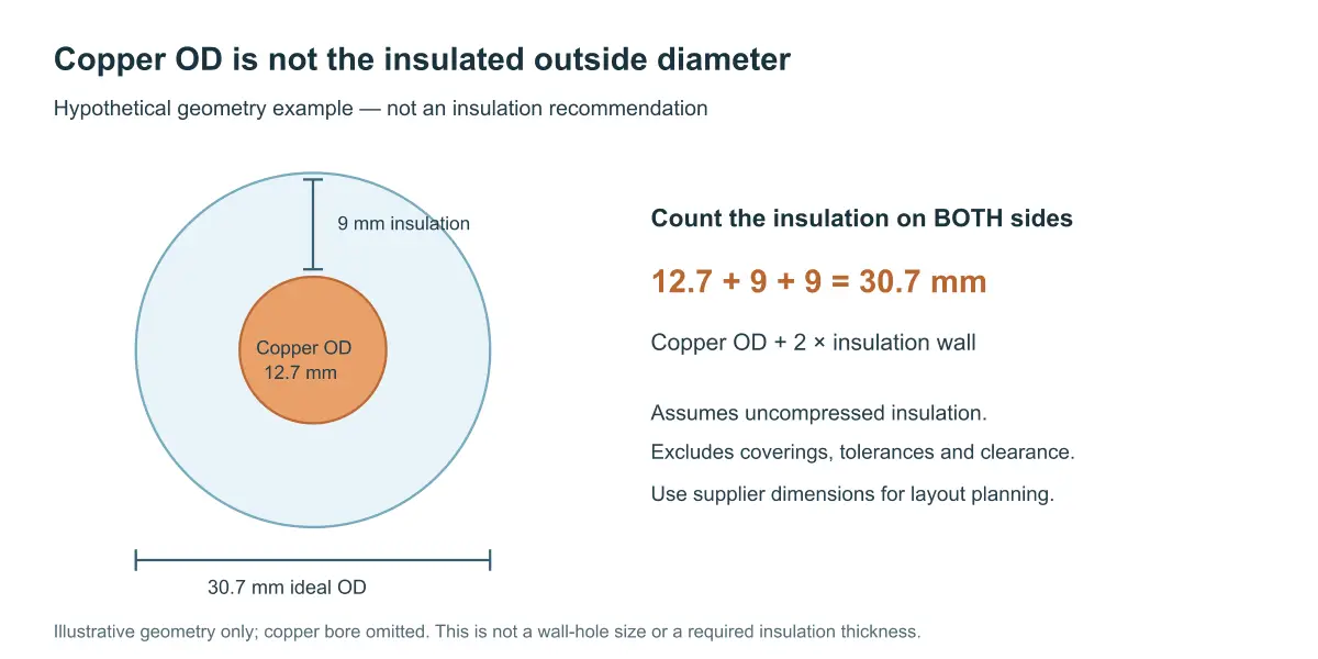
For a hypothetical geometry check, take a 12.7 mm copper OD and an uncompressed 9 mm insulation wall. The ideal outside diameter of that insulated leg is 12.7 + 2 × 9 = 30.7 mm. This calculation excludes manufacturing tolerances, external coverings, and installation clearances; it is not a recommended insulation thickness or wall-hole size.
The calculation explains why cover clearance cannot be read from the copper chart alone. Use the supplier’s finished dimensions and the installation layout when selecting covers and penetrations.
Copper size and connector identification
A flare nut’s wrench size is not its copper-tube OD. A proprietary coupling marking can identify a connector family rather than the bare tube. Keep those identification systems separate when comparing spare parts or reading tightening tables.
In particular, do not choose a torque by matching a familiar fraction on a coupling to a copper-size row from an unrelated flare chart. Use the equipment’s connection instructions and the identification method they specify. This diameter chart does not supply tightening values.
Turn the Selected Pair Into an Unambiguous Order
Once the equipment requirements are confirmed, describe both tubes, their specified walls and material condition, the required supplied length, insulation, and end arrangement. For pre-flared material, identify the required nuts and protected delivery condition. Keep the approved equipment reference with the item.
Nexnice can discuss these dimensions and end-preparation choices through its insulated copper line set range. The useful starting point is the confirmed pair and specification, not an instruction to select piping from capacity alone.
At receipt, compare the two labeled diameters and end arrangements with that item description. If one leg or connector differs, hold the affected assembly for clarification. Do not conceal a mismatch by relabeling it as a general-purpose mini split kit.
Conclusion: Use the Chart to Identify, Then Verify
The five pairs provide a clear dimensional vocabulary. The equipment documentation decides which pair is permitted. Keeping those tasks separate prevents a convenient comparison chart from becoming an unsupported sizing rule, and keeps every subsequent accessory choice tied to the intended assembly.
Frequently Asked Questions
What does a 1/4 × 3/8 line set mean?
It normally describes two copper outside diameters: 1/4 inch for the liquid line and 3/8 inch for the gas line. Confirm the listing order. The numbers do not specify tube wall, insulation thickness, length or connection type.
Is 9.52 mm the same label as 3/8 inch?
Catalogs often use 9.52 mm as a rounded label for 3/8 inch tubing. The exact conversion is 9.525 mm. Retain the governing specification and its tolerances; a rounded display number should not silently redefine dimensional acceptance.
Which size fits an 18,000 BTU mini split?
Check the complete model’s installation documentation. The Pioneer examples discussed here have different gas-line sizes despite sharing the 018 model designation. Capacity can locate the relevant product entry, but it cannot establish a universal liquid-and-gas pipe pair.
Can I use a larger gas line?
Only when the equipment manufacturer permits that arrangement. A larger diameter is a change to the specified piping, even if an adapter makes it connect. Confirm the complete route and required connections instead of assuming larger means better performance.
Does insulation color identify the copper size?
No reliable size identification follows from color alone. Read the product label and specification, then verify dimensions by the agreed inspection method if necessary. The outer covering can hide tubes of different diameters and different insulation wall thicknesses.
Confirm Your Required Diameter Pair
Share the full equipment reference and its liquid/gas piping requirements with Nexnice. Add tube-wall, insulation and end-preparation details to your line set sizing enquiry so the proposed assembly can be compared directly with the approved schedule.