
A mini split line set connects the refrigerant circuit between the indoor and outdoor units. Choosing it means matching a complete assembly to a particular system: two pipe diameters, an installed length, insulation and compatible connections. A coil that reaches both units can still be unsuitable.
This mini split line set guide brings those decisions together for contractors, distributors, and project buyers. It covers conventional copper line sets and the distinction between ordinary flared connections and specific factory-charged quick-connect systems. The 2026 reference point means checking the documentation for the equipment actually being supplied; an older installation sheet or a similar-looking fitting cannot establish compatibility with a new model.
Executive Summary
- Identify both equipment models and the specified refrigerant before choosing a line set.
- Match both copper outside diameters; capacity alone does not determine the pair.
- Check the route against minimum length, maximum length, elevation, and charge conditions separately.
- Select insulation for the operating and surrounding conditions, including exposed joints and outdoor sections.
- Use the connection and commissioning process specified for that system, then keep the route accessible for inspection.
What a Mini Split Line Set Includes
Two refrigerant paths
A typical copper line set contains a smaller and a larger tube. Manufacturers commonly describe these as the liquid and gas lines. Use the names and sizes in the equipment documentation when identifying them, especially on heat pumps whose operation changes between heating and cooling.
The pair designation describes the copper outside diameters. It does not describe the insulation thickness, the dimensions of the finished bundle, or the size of a coupling nut. Our five-pair line set size chart explains how to read these dimensions and compare them with the selected equipment.
Insulation belongs to the assembly specification too. The reviewed Daikin installation manual requires both refrigerant pipes to be insulated. One bare tube beside one insulated tube should therefore never be accepted simply because it resembles another type of air-conditioning installation. Follow the instructions for the exact system.
A kit is a packaging description
A mini split line set kit may include pre-flared ends, flare nuts, cable, drain hose, wrapping materials, or a wall sleeve. The word “kit” does not guarantee any particular accessory. Compare the supplied contents with the installation schedule before delivery.
Keep the three routes conceptually separate: refrigerant moves through the copper, condensate leaves through a drain, and electrical or communication connections have their own requirements. Packaging them together does not make one specification cover all three. A supplied cable still needs to match the equipment instructions and installation requirements.
For a replacement project, photograph the equipment labels and identify the existing route before ordering. A seller may be able to reproduce the visible assembly, but matching an old assembly is useful only after its suitability has been checked.
Start With Compatibility, Then Measure the Route
Are mini split-line sets universal?
No. Matching diameters is necessary, but it does not settle tube wall, cleanliness, refrigerant suitability, connector design, or permitted length. Even within one manufacturer’s range, the required gas-line size can vary between models with similar capacity descriptions.
Begin with the indoor and outdoor model pairing, the installation manual, and any approved accessory schedule. Record the liquid and gas pipe requirements from those documents. If the equipment arrives with a different model suffix or refrigerant designation, resolve that change before treating the original line-set order as suitable.
This is particularly useful when a distributor carries several equipment generations at once. The equipment documentation reviewed for this guide identifies refrigerants and pipe requirements for the relevant product families. A stocking rule based only on a familiar capacity label would lose that distinction.
Are all mini split line sets copper?
Copper is the tubing material used in the equipment instructions and product examples reviewed here. That observation is not evidence that every product sold under the phrase “mini split line set” has the same construction. Confirm the material in the specification rather than inferring it from a copper-colored exposed end.
A proposed alternative construction needs explicit acceptance for the equipment and service conditions. A nominally matching diameter, an attractive coating, or an unqualified pressure claim cannot establish that approval. The same principle applies to reusing existing tubing: suitability depends on its documented condition and the equipment manufacturer’s instructions.
Once the assembly type is established, use the minimum and maximum length guide to evaluate the actual route. Length is a system constraint, not just a convenient coil size.
Match the Pipe Pair Before Comparing Prices
Capacity is a starting clue
Capacity can help locate a model in a manufacturer’s table, but it is not a universal pipe-sizing formula. A published size chart for one product family should not be extended to another family without checking its documentation.
The useful question is whether each specified pipe matches each required connection. Record the smaller and larger outside diameters independently. If a listing displays only one number, ask what it refers to. It may describe one tube, a fitting, or an accessory rather than the complete pair.
Changing the gas line while retaining the liquid line creates a different assembly. Neither “close enough” nor “larger should be better” is a sound substitution rule. A reducer can change a connection geometry without proving that the resulting pipe arrangement is permitted.
Include the insulation envelope
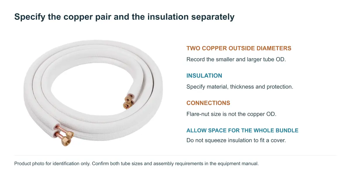
The space needed through a wall or inside a cover is larger than the bare copper diameters. Insulation, the gap between the tubes, and any separately routed cable or drain, all influence the installation envelope.
Check the available space before choosing a cover or penetration detail. A route that works for bare tubes may squeeze the insulation at a corner or leave too little room to make the turn. Compressing insulation to force the assembly into a narrow channel undermines the very thickness selected for thermal performance.
Nexnice’s documented insulated copper line set options include configurable tube dimensions, insulation, and end preparation. Use the approved equipment schedule to define those options; a configurable product range does not make every combination compatible with every mini-split.
Choose Length From the Installed Path
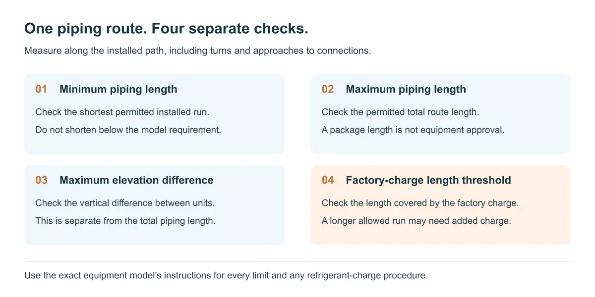
Four limits answer different questions.
Measure along the intended piping route, including changes of direction and the approach to each connection. Straight-line distance between the units is insufficient when the pipe follows walls, crosses a ceiling, or passes around an obstruction.
Then distinguish four values: the manufacturer’s minimum piping length, maximum piping length, maximum elevation difference, and the length supported by the factory refrigerant charge. The last value may be shorter than the maximum permitted route. A permitted longer installation can therefore require an additional charge under the manufacturer’s procedure.
For illustration, the reviewed Daikin RXM09WVJU9/RXM12WVJU9 manual separates a 3 m minimum, 25 m maximum, 20 m elevation limit, and 15 m charge threshold. These values belong to the listed models. They demonstrate the four separate checks; they are not defaults for other systems.
Excess length needs an approved arrangement
Choosing a 50 ft package does not mean that 50 ft must always remain in the finished installation. A conventional uncharged line set may be cut and re-prepared when the equipment instructions allow it and the work preserves the required minimum length and cleanliness.
A factory-charged proprietary assembly is different. Do not assume it can be shortened like an ordinary uncharged coil. Its manufacturer may specify available lengths, approved extension components, and how excess tubing must be arranged.
The installation drawing should show the final routing and any retained surplus. Leave room for supported bends and service access, rather than discovering after connection that the spare length has nowhere suitable to go.
Select Insulation for the Actual Environment
Material names do not establish performance
PE and rubber are material-family labels. The useful comparison concerns the particular product’s thermal conductivity, operating temperature range, moisture behavior, thickness, and protective facing. A black surface does not by itself prove superior insulation, and a white facing does not establish outdoor durability.
Compare data at the stated test conditions. Thermal conductivity values measured at different mean temperatures are not directly equivalent. Likewise, a water-vapor permeability result and a water-vapor resistance factor describe different quantities; their raw numbers cannot be ranked against each other.
The PE and rubber insulation comparison develops these selection questions. At the overview stage, define the expected pipe temperatures and the surrounding temperature and humidity, then ask for a thickness recommendation covering those conditions.
Continuity matters at joints and supports
Pre-insulated straight sections do not finish the entire job. Connections, cut ends, bends and supports can leave local gaps or compressed areas. The installed system needs the sealing and support details specified for the insulation product.
Outdoor exposure adds another question: what protects the selected material from sunlight, rain and physical damage? Some products incorporate a tested facing; others require an approved coating or cladding. A decorative cover may protect a route, but it does not automatically replace the insulation manufacturer’s weatherproofing instructions.
Inspect the insulation after routing and connection, before it becomes difficult to reach. This is the point at which a stretched seam or a tight tie can still be corrected without reopening a finished wall or removing a long cover section.
Choose the Correct Connection Workflow
Conventional flared connections
A conventional flare joint uses a formed copper end and matching nut and seat. The correct pipe size is only part of the connection: preparation, alignment, surface condition and the specified tightening method also matter.
An outdoor unit containing a factory refrigerant charge does not mean the attached conventional line set is already charged or that evacuation can be skipped. The installer must follow the equipment’s leak-testing, evacuation and valve-opening sequence before commissioning.
Keep the joints accessible until the required checks are complete. Covering them early makes inspection harder and can hide a connection that needs correction. Joint insulation is completed as part of the prescribed finishing sequence.
Factory-charged quick-connect assemblies
Some systems use designated factory-charged lines and proprietary couplings. Their instructions can remove particular field operations from the initial installation, but only for the compatible, intact assembly described by that manufacturer.
“Quick-connect” does not establish a universal connector standard or a universal no-vacuum procedure. Confirm the system generation, refrigerant, line-set part number and coupling requirements. The reviewed MRCOOL DIY fifth-generation manual also restricts its quick connectors to a single installation; a convenient initial connection should not be mistaken for unlimited disconnect-and-reconnect service.
Our flared and quick-connect installation comparison explains the differences in preparation, torque references, commissioning and later service. Choose the workflow before buying tools or scheduling installation labor.
Route the Tubing Without Creating Damage
Plan the turn before making it
Soft copper permits routing changes, but it can still flatten or kink. Unroll the coil in a controlled way and keep the ends protected. Pulling a tight loop straight by its ends can concentrate the bend in one short section.
Check the minimum bend radius specified for the assembly and use a suitable forming method for its copper dimensions and condition. Published instructions sometimes provide a fixed minimum radius for a particular product; that number should not be applied to every tube and tool.
Avoid repeatedly adjusting the same point to make an awkward route fit. If the wall opening or cover leaves insufficient turning space, revise the layout before forcing the tubing. The line set bending guide covers preparation, tool selection and inspection in more detail.
Protect the finished shape
Supports should retain the route without crushing insulation or loading the equipment connection. Check penetrations and cover edges for rubbing points. A bend that looks acceptable before the cover is fitted may be displaced when the cover is closed.
Do not hide a visibly kinked or damaged area inside insulation. Record its location and have the responsible installer determine the corrective work before commissioning. A successful leak check alone would not prove that a flattened pipe still has an acceptable flow passage.
Care Starts With a Useful Handover Record
Keep the equipment model numbers, installed line-set dimensions, final route length and commissioning record together. Include photographs of concealed portions and accessible connection locations. These details make later diagnosis more specific than a note saying “standard mini split pipes.”
During routine inspection, look for damaged coverings, open insulation seams, displaced supports and unexpected water. The observation should guide the next check. It should not immediately become a diagnosis of low refrigerant, defective copper or an unsuitable insulation material.
Locate the source of water
Condensation can form where an exposed surface is colder than the surrounding air’s dew point. However, water near a line set can also come from the condensate drain or a rainwater entry path. Identify where the water first appears, rather than relying on where it finally drips.
If moisture appears only at a seam or a compressed support, inspect that local detail. If it covers a broad insulated section, compare the operating and ambient conditions with the insulation design. The line set condensation troubleshooting guide gives a focused sequence for separating those possibilities.
An equipment fault requires a different investigation from an insulation defect. Icing, poor cooling or an error indication should be referred to the equipment’s service process; adding more outer tape is not a diagnosis.
Conclusion: Specify the Assembly as a System Component
A suitable mini split line set combines the right copper pair, an allowed route, appropriate insulation and the intended connections. Those decisions should agree before the assembly reaches the site. After installation, preserve the same clarity in the handover record so future inspection can distinguish equipment, piping, insulation and drainage issues.
Frequently Asked Questions
What is a mini split line set?
A mini split line set is the refrigerant piping assembly linking the indoor and outdoor units. It commonly contains two copper tubes with insulation. Cable, drain hose and installation accessories may accompany a kit but need separate specification checks.
Can one line set fit several brands?
It may fit more than one approved application, but brand names alone cannot establish compatibility. Compare both pipe diameters, tube requirements, refrigerant service, connection design and allowed length against each equipment manual before using the same assembly across systems.
Does a longer line set improve installation flexibility?
Extra supplied length can provide routing options, but the finished run must still meet equipment limits and charge requirements. It also needs suitable space and support. Choose from a measured route instead of treating the longest available coil as automatically preferable.
Does pre-insulated mean ready to commission?
No. Pre-insulation covers a supplied portion of the assembly. Connections, insulation joints, leak checks and the equipment’s commissioning procedure still require attention. A factory-insulated product does not establish that the refrigerant circuit has been correctly installed or tested.
Should old line sets always be replaced?
Follow the new equipment manufacturer’s instructions and assess the existing assembly’s documented condition. Diameter alone cannot establish cleanliness, wall suitability or connection compatibility. Where the manual prohibits reuse, an apparently undamaged old route does not override that requirement.
Discuss a Line Set Specification
Send Nexnice the equipment piping schedule, required pair and length, insulation conditions and end-preparation requirements. The line set project enquiry can then focus on a defined assembly, with compatibility confirmed against the equipment documentation before an order is finalized.