
When a heat exchanger drawing reaches the tube line, the specification can look deceptively short: alloy, outside diameter, wall thickness, length and temper. Those fields describe the tube, but they do not describe the job the tube must do. A copper tube heat exchanger may carry boiling refrigerant through a finned coil, move glycol through a shell-and-tube bundle, sit as a coil inside a storage tank, or work as one side of a compact coaxial circuit. Each arrangement creates a different balance between heat transfer, pressure drop, forming, joining, fouling and service access.
We work from the factory side, so we start with the operating duty and the finished assembly rather than with a catalogue diameter. This guide explains the common copper tube heat exchanger types, how tube geometry changes the thermal and hydraulic result, which materials and standards engineers usually compare, and what an OEM should freeze before asking a supplier to quote a production part. A broader tube taxonomy helps, but the exchanger-specific decisions below should follow the duty and flow path.
Executive Summary
- Choose the exchanger arrangement before choosing a tube size. A finned air coil, shell-and-tube bundle and immersion coil do not use the same design logic.
- Match alloy and temper to the fluid, pressure boundary, forming route and joining process. Copper conductivity alone does not decide the specification.
- Check outside diameter, wall, circuit length and surface profile together because each changes area, velocity, refrigerant volume and pressure drop.
- Use smooth, finned or inner-grooved tube only when the expected resistance reduction is supported by the actual duty and flow range.
- Give the manufacturer the fluid schedule, design pressure, temperatures, flow rates, allowable pressure drop, fouling conditions, drawing and inspection basis.
What Is a Copper Tube Heat Exchanger?
A separated path for two fluids
A copper tube heat exchanger transfers heat across a metal wall while keeping the two working fluids physically separate. Refrigerant, water, glycol, oil or another process fluid travels inside the tube. Air, tank water, shell-side liquid or a second process stream contacts the outside. The heat path includes convection on the first side, conduction through the tube wall and convection on the second side.
That simple definition matters in B2B design work because the tube is only one part of the thermal resistance network. A high-conductivity tube cannot correct poor airflow, uneven refrigerant distribution, a blocked water passage or a badly supported joint. ASHRAE describes exchanger selection through the relationship between overall heat-transfer coefficient, heat-transfer area and the log mean temperature difference. The tube specification has to support all three terms.
Why copper is used in HVACR
Copper combines high thermal conductivity with a useful manufacturing profile. It can be drawn to controlled dimensions, supplied in straight lengths or coils, formed into return bends, expanded into fins, and joined by brazing. That combination lets an equipment builder use the same basic material in a condenser, evaporator, heat-pump coil, tank coil or shell-and-tube bundle. For a broader sizing vocabulary, our reference for copper tube dimensions helps teams align OD, ID and wall terms before they compare exchanger drawings.
The practical value shows up at the interfaces. A tube that can be formed without excessive flattening keeps the intended flow area. A clean internal surface protects small passages and expansion devices. A predictable temper helps the tube survive bending, expansion and brazing without an unexpected crack or loss of shape.
Sensible and latent heat duties
Some exchangers transfer sensible heat between two liquids or between a liquid and air. Others handle latent heat, where a fluid boils or condenses. Refrigeration coils often move through superheat, two-phase change and subcooling zones in one circuit. The density, velocity and pressure drop do not stay constant from inlet to outlet, so the tube cannot be selected from one average condition alone.
Which Copper Tube Heat Exchanger Types Are Used?
Finned air-to-refrigerant coils
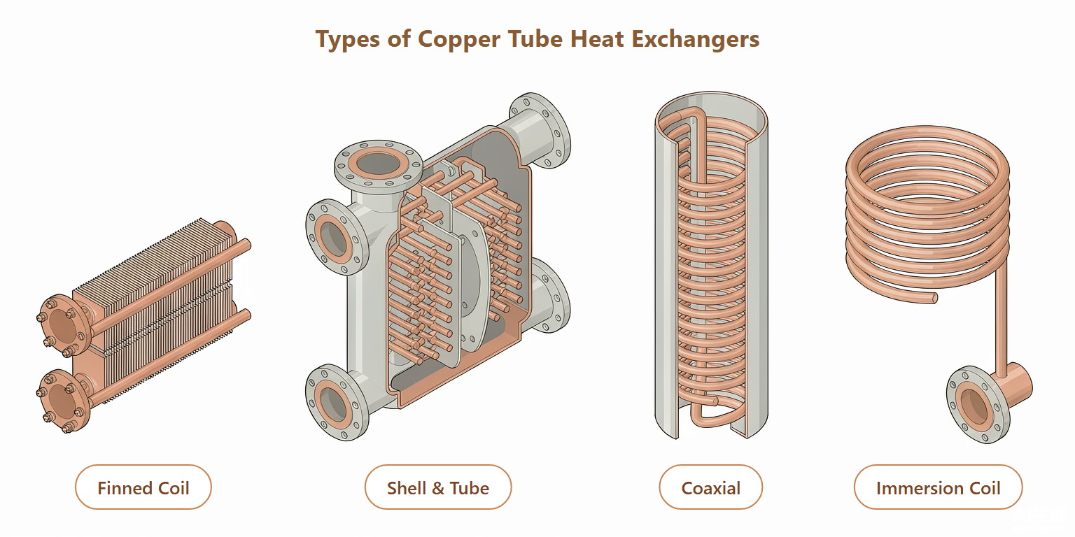
Finned coils place copper tubes through aluminum or copper fins. Refrigerant or water travels inside the tube while air crosses the fin pack. The coil designer must balance tube diameter, row depth, fin pitch, circuit length, return-bend layout, header distribution and face velocity. A smaller tube can increase surface-to-volume ratio, yet the circuit may need more branches to keep pressure drop and distribution under control. The cluster article on matching tube material and size to exchanger duty expands that decision with the fluid and performance constraints in view.
For a heat pump, the same coil may operate as a condenser in one mode and an evaporator in another. That reversal changes the preferred circuiting, oil movement and frost or condensate behavior. The tube drawing should therefore be checked against both operating directions when the equipment uses a reversing valve.
Shell-and-tube heat exchangers
Shell-and-tube units place a tube bundle inside a shell. Baffles guide the shell-side fluid across the tubes, while the tube-side fluid follows one or more passes. The bundle can use U-tubes, straight tubes or a removable arrangement. Tube diameter, gauge, pitch and material affect the heat-transfer coefficient, velocity, pressure drop and mechanical joint at the tubesheet.
The design priority is often serviceability as much as thermal area. A small-diameter, long-tube bundle can provide efficient heat transfer, but the shell still needs clearance for inspection or bundle removal. If the water contains suspended solids, tube diameter and cleaning access become part of the selection rather than a later maintenance issue. Readers comparing compact formed circuits can also see how coil geometry changes the heat exchanger layout before they freeze a bundle drawing.
Coaxial and tube-in-tube designs
Coaxial exchangers use one tube inside another, often with counterflow between the two passages. They suit heat pumps, water-source systems and compact process loops where a packaged coil is easier to install than a large bundle. Concentricity, annular clearance, brazed joints and the direction of each flow path determine whether the available length is being used effectively.
Double-wall versions add a visible or vented leak path between the fluids. That design can be useful where cross-contamination must be detected, although the extra wall changes thermal resistance and cost. The manufacturer needs the fluid compatibility and pressure relationship on both sides before recommending a tube arrangement.
Immersion and tank coils
An immersion coil keeps the working fluid inside the copper while the outside of the coil sits in a storage or process tank. Natural convection depends on coil pitch, vertical spacing and clearance from the tank wall. Pumped circulation adds local velocity but also introduces forces on the supports and connections. The cluster discussion of tank coil circulation and support details follows those choices through the finished assembly.
Scale and water chemistry can dominate the long-term result. Adding more copper length does not restore capacity if a thick deposit forms on the outside surface and the operator cannot clean it. Tank volume, treatment plan, removable access and drainability belong on the coil drawing.
| Exchanger format | Typical copper tube role | Main design variable | Service question |
|---|---|---|---|
| Finned air coil | Refrigerant or water circuit through fins | Circuiting, fin contact and airflow | Can the coil be cleaned and defrosted? |
| Shell-and-tube | Tube bundle between tubesheets | Tube pitch, passes and baffles | Can the bundle be inspected or removed? |
| Coaxial or tube-in-tube | Inner or annular flow path | Concentricity and counterflow length | Can both circuits be brazed and pressure-tested? |
| Immersion coil | Formed coil inside a tank | Pitch, circulation and water chemistry | Can the coil be supported and cleaned? |
How Does Copper Tube Geometry Affect Heat Transfer?
Outside diameter sets area and velocity
At a fixed length, a larger outside diameter provides more external area. The same change also increases internal volume and can lower velocity at a given mass flow. A smaller diameter raises the surface-to-volume ratio and may improve refrigerant-side heat transfer, but it can add restriction and make distribution more sensitive. Engineers normally compare OD, wall, circuit length and parallel-circuit count as one design set.
The relationship is easy to miss when a buyer compares only nominal size. Two tubes with the same OD can have different IDs because their walls or internal profiles differ. That changes flow area, velocity, refrigerant charge and pressure drop. The OD, ID and wall comparison chart is useful when an OEM translates a coil drawing into a tube purchase specification.
Wall thickness protects the pressure boundary
Wall thickness carries pressure, supports the tube during forming, and leaves material for brazing or expansion. The required value depends on design pressure, temperature, alloy, temper, tube support and applicable code or standard. A thinner wall may reduce thermal resistance and weight, but it leaves less margin for forming damage, corrosion allowance or a high-pressure refrigerant duty.
The drawing should state the nominal wall, minimum wall if applicable, tolerance basis and the location where the measurement is taken. On a formed coil, the bend can become the critical area. An incoming straight-tube report alone cannot prove that the final hairpin or coil still meets the pressure design.
A smooth tube is the calculation baseline
A smooth tube remains a strong option when the exchanger has enough surface area, needs mechanical cleaning, uses established brazing procedures or operates with fluids that make a textured surface difficult to inspect. Its internal geometry is easy to measure and its pressure-drop model is familiar to most equipment designers.
That does not make smooth tube automatically better. If the air side is already the dominant resistance, adding an enhanced internal surface may produce little system-level benefit. The engineering team should show which resistance the proposed change reduces and what pressure-drop penalty it adds.
Inner grooves change the internal flow
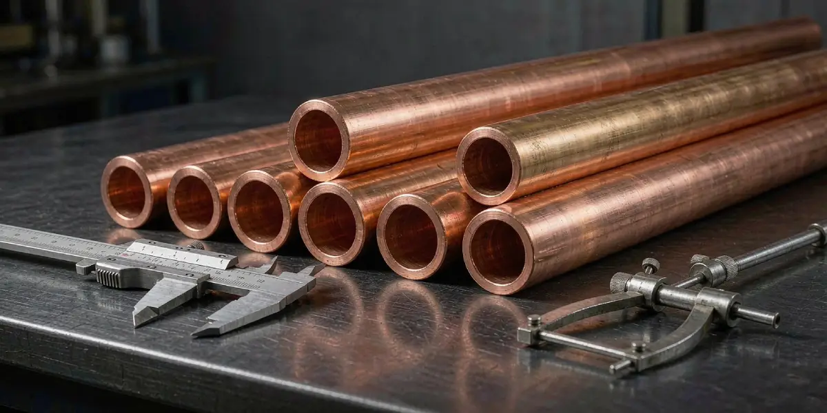
An inner-grooved or micro-fin tube adds engineered surface and disturbs the internal boundary layer. In suitable boiling and condensing duties, the profile can increase the refrigerant-side coefficient and support a more compact circuit. The benefit depends on groove depth, helix, root wall, mass flux, oil circulation, refrigerant and length. The inner-groove heat-transfer discussion looks at that profile and its performance trade-offs.
For a production decision, the profile still needs to be checked against the actual drawing and duty. The profile should be measured at the tube root and crest, and the plain end should be long enough for the selected fitting or header joint.
Fins only work when contact is controlled
External fins enlarge the air-side surface. Mechanical expansion, welding or another joining process must create consistent contact between fin and tube. A loose interface leaves an air gap; excessive expansion can distort the tube or change its internal area. Fin material, fin pitch, expansion method and allowable tube deformation should appear together in the coil specification.
Which Copper Materials and Tempers Fit HVACR Heat Exchangers?
C12200 DHP copper for common ACR duties
Phosphorus-deoxidized copper, commonly identified as C12200 or Cu-DHP, is widely used for air-conditioning and refrigeration tubing. Copper Development Association guidance describes ACR tube under ASTM B280 as C12200 material, with coils commonly supplied annealed and straight lengths supplied in a hard temper. The exact tube condition still depends on the drawing, pressure design and forming route.
The phosphorus content improves suitability for brazing compared with oxygen-bearing copper in many HVACR applications. The final specification should still identify the required alloy, temper, cleanliness and test documentation rather than relying on the phrase “refrigeration copper.”
Temper follows the forming route
Annealed tube is easier to coil, bend and form in place. Hard-drawn tube keeps a straighter shape and can suit straight runs or assemblies that need rigidity. A shell-and-tube bundle, a finned hairpin coil and a small capillary circuit may all use copper while requiring different tempers.
The forming process can change the tube after it leaves the mill. Bending introduces ovality and springback. Expansion into a fin pack changes the local wall and surface contact. Brazing heats the joint and nearby tube. The sample used for approval should reflect the final process, not only the incoming material.
Fluid compatibility limits the choice
Copper works with many refrigerants, water and glycol systems, but it is not a universal choice for every fluid. CDA guidance specifically cautions against ammonia service for copper tube. Process-water chemistry, chlorides, pH, suspended solids and cleaning chemicals can also change the corrosion risk. When the outside environment is more aggressive than the inside fluid, the coil may need a coating, isolation or a different alloy.
| Material or condition | Where it often fits | What the engineer must confirm |
|---|---|---|
| C12200 annealed copper | Coils, hairpins and formed circuits | Brazing, bend radius, ovality and pressure |
| C12200 hard-drawn copper | Straight lengths and rigid assemblies | Tube-sheet fit, straightness and joint method |
| Inner-grooved copper | Compact boiling or condensing circuits | Profile, root wall, pressure drop and oil return |
| Copper alloy or alternative material | Aggressive or high-pressure fluid cases | Compatibility, code, joining and supply availability |
How Do Engineers Size a Copper Tube Heat Exchanger?
Start with duty and approach temperature
The first calculation is the heat balance: required capacity, entering and leaving temperatures, mass flow and fluid properties. For a sensible liquid duty, the heat load follows the fluid heat-capacity change. For a refrigerant duty, the enthalpy change across the evaporator or condenser controls the required mass flow and surface area.
ASHRAE explains that the log mean temperature difference affects the area required for a given load. A close approach temperature usually requires more effective area. It can also increase the influence of tube-to-fin contact, fouling and temperature distribution. A supplier can compare tube options only after the duty basis is clear.
Check velocity and pressure drop together
Velocity drives convection and helps carry oil or suspended material, yet excessive velocity raises pressure drop, noise and erosion risk. A shell-and-tube unit may use baffles and multiple passes to increase shell-side velocity, while a finned refrigerant coil may use parallel circuits to keep the pressure loss within the compressor or expansion-device limit.
The tube choice should be checked at minimum and maximum flow. A circuit that performs well at rated capacity may lose oil return at low load or exceed pressure drop during a hot pull-down. We prefer a table that shows design, part-load and transient conditions instead of one average velocity.
Model phase change along the circuit
A condenser may include desuperheating, condensation and subcooling zones. An evaporator may include a two-phase region followed by superheat. Each zone changes density, local heat-transfer coefficient and pressure drop. Circuiting, header distribution and return-bend count should be checked against those regions rather than selected from a single overall coefficient.
Heat pumps add another layer because the coil can reverse its role. The distributor, header and oil-return logic must work in both directions if the system is designed for heating and cooling. A tube manufacturer can support the geometry review, but the equipment designer owns the system-level circuit calculation. The condenser and evaporator tube comparison separates the two duties and their tube requirements.
Allow for fouling and water quality
Fouling adds thermal resistance and can restrict flow. ASHRAE recommends considering fouling allowance during selection and stresses that water quality must be compatible with the exchanger materials. For a tank or shell-side water duty, specify treatment, solids, cleaning method and service interval. For a refrigerant circuit, cleanliness and capped ends are part of the same performance discussion.
Leave room for maintenance
The most efficient tube arrangement can become a poor factory decision if the bundle cannot be removed or the coil cannot be inspected. Shell clearance, header access, drainability, venting, fin cleaning and connection orientation should be frozen before the tube length is final. The exchanger must fit the service plan and the thermal model.
What Standards Cover Copper Heat Exchanger Tubes?
ASTM B280 for ACR field-service tube
ASTM B280 is commonly referenced for seamless copper tube used in air-conditioning and refrigeration field service. The specification covers material, dimensions, mechanical properties, cleanliness and identification requirements used by the HVACR supply chain. The purchase order should name the edition and any supplementary tests rather than using “ASTM copper” as a general phrase.
CDA’s public standards guidance explains that ACR tube is cleaned and capped before shipment and that C12200 is the normal alloy basis. Those details matter because a clean, sealed tube protects the refrigeration circuit from particulate and moisture introduced during storage or assembly.
ASTM B359 for integral-fin tube
ASTM B359 covers seamless copper and copper-alloy condenser and heat-exchanger tubes with integral fins. When the tube surface itself carries the fin geometry, the specification must be read together with the profile drawing, fin dimensions, joining method and finished-part inspection plan.
EN 12735-2 for equipment tubing
EN 12735-2 covers seamless round copper tubes for air-conditioning and refrigeration equipment. European projects may also require material certificates, cleanliness evidence, dimensional reports or pressure-test records tied to the actual lot. The correct standard depends on the destination market and the equipment designer’s compliance route.
Standards do not replace the component drawing
Standards define a controlled product range, but they do not choose the circuit length, header, fin pitch, bend radius, coating or tank support. A tube can meet a material standard and still be unsuitable for a particular exchanger if the forming route, joint or operating envelope is wrong.
| Reference | Typical relevance | Still needed on the project drawing |
|---|---|---|
| ASTM B280 | ACR field-service tube | Alloy, temper, size, cleanliness and cap requirement |
| ASTM B359 | Integral-fin condenser or heat-exchanger tube | Fin profile, root wall and joint details |
| EN 12735-2 | European HVACR equipment tubing | Edition, dimensional class and documentation |
| Project specification | Finished coil or bundle | Circuit, supports, connections, tests and packing |
How Do Applications Change Tube Selection?
Air-conditioning and refrigeration coils
The main decisions are fin-side airflow, refrigerant distribution, circuit length, pressure drop, frost or condensate management and joint repeatability. A finned coil supplier needs the coil face, row count, fin material, circuit schedule and operating envelope. A tube supplier needs the OD, wall, temper, surface profile, coil form and end preparation that the coil builder will actually use.
Heat pumps and reversible equipment
Reversible equipment can make one coil serve as both evaporator and condenser. That means the tube circuit must tolerate changing phase distribution and oil movement. Small-diameter or inner-grooved tube may support a compact design, but the distributor, header and control strategy have to be evaluated in both modes. A condenser and evaporator tube comparison can help when the equipment uses one reversible coil.
Water, glycol and process loops
Liquid duties place more attention on velocity, water chemistry, cleaning and corrosion. Shell-and-tube designs may favour straight or U-tubes with serviceable heads. Coaxial and immersion coils suit compact equipment or tanks, but the designer must show circulation, support and drainability. Glycol concentration changes viscosity and therefore pressure drop, so it belongs in the fluid schedule.
Industrial and equipment cooling
Process skids, heat-pump water heaters, data-center cooling loops and packaged thermal equipment may need a compact exchanger with a known service path. A copper tube solution can be attractive when thermal conductivity, forming and brazing fit the duty, but high pressure, aggressive fluids or strict cross-contamination requirements may lead to a different material or double-wall construction.
What Manufacturing Details Protect Heat-Exchanger Performance?
Forming must preserve the flow area
Coiling, hairpin bending and U-bending change the tube geometry. The approved process should state bend radius, tooling direction, allowable ovality, springback and the location of straight ends. If the customer forms the coil after delivery, the payoff method and minimum bend radius belong in the supplier specification.
Joining is part of the tube design
Return bends, headers, tubesheets and fittings need a controlled insertion length and compatible filler or expansion method. An inner-grooved tube may need a plain end for the joint. A shell-and-tube bundle may need a tube end that can be expanded or welded into a tubesheet. The sample should include the real joint interface, because a straight tube coupon cannot show the final distortion or leak path.
Cleanliness starts before packing
Cutting debris, oxide, oil, moisture and open ends can create problems in a refrigeration or small-passage circuit. Tube ends should be inspected, cleaned and capped according to the agreed procedure. Packaging should protect the caps, coil layers and labels through handling and ocean transport. Those steps are production controls, not decorative packing upgrades.
Quality records must follow the lot
For a production release, the useful record set normally includes material identity, dimensional results, surface or profile checks, pressure or leak testing, joint or forming approval, packaging identity and any deviation record. The sampling plan should name the measurement method and locations. A report without the gauge basis is difficult to compare with the next lot.
How Should an OEM Specify a Copper Tube Heat Exchanger?
The engineering handoff should describe the finished duty and the tube interface in one controlled package. A manufacturer can then separate a standard tube quotation from custom forming, new tooling or a development sample.
- Exchanger type, fluid pair, duty and operating envelope
- Design and test pressure, temperature range and allowable pressure drop
- Tube alloy, temper, OD, wall, tolerance, length and surface profile
- Circuit, bend, header, tubesheet, fin or tank interface
- Cleanliness, caps, packaging, inspection records and change-control rules
Keep the commercial part short. Price, MOQ, lead time and shipping terms matter after the technical scope is stable; they cannot rescue a tube that fits the wrong circuit or arrives with an unprotected bore. At Nexnice, a technical review can check the drawing, material, forming route and required documents before a quotation is finalized. The same review helps an OEM distinguish a standard product from a part that needs a sample approval. For coil projects, the ACR copper coil range provides a concrete reference for C12200 material, coil form and protective packaging.
Copper Tube Heat Exchanger Selection: Final Summary
A copper tube heat exchanger works as a system of thermal, hydraulic and mechanical decisions. The exchanger type sets the flow path. The duty sets the required area and temperature approach. Tube OD, wall, temper and surface profile set the balance between transfer, pressure drop, forming and service. Water chemistry, refrigerant phase change, fin contact, cleanliness and connection design determine whether that balance survives production and field operation.
For a reliable specification, start with the duty and flow path, then select the tube form and material. Check the complete circuit at rated, minimum and transient conditions. Name the applicable standard and the finished-part tests. Finally, make sure the supplier sees the actual drawing and the actual joining or forming route. That sequence produces a tube that can be manufactured, inspected and installed with the same assumptions.
Frequently Asked Questions
What is a copper tube heat exchanger?
A copper tube heat exchanger transfers heat between two separated fluids through a copper wall. Engineers use it in finned coils, shell-and-tube bundles, coaxial units and tank coils because copper combines thermal conductivity with controlled drawing, bending and brazing. The final performance still depends on circuiting, airflow, velocity and fouling.
Which copper tube is best for a heat exchanger?
There is no single best tube for every exchanger. C12200 DHP copper is common in HVACR, while the correct OD, wall, temper and surface depend on pressure, fluid, forming, joining and cleaning. Smooth tube suits simple or serviceable designs; inner-grooved tube needs a duty calculation that justifies its profile.
Are copper tubes suitable for shell-and-tube heat exchangers?
Yes, copper tubes are widely used in shell-and-tube bundles for compatible water, glycol and refrigerant duties. The designer must still check tube-sheet fit, baffle velocity, pressure, water chemistry, vibration and cleaning access. Suspended solids or aggressive fluids may require a different alloy, coating or exchanger construction.
Do inner grooves always improve heat transfer?
No. Inner grooves can raise the refrigerant-side coefficient in suitable boiling or condensing conditions, but they also change pressure drop, oil movement, cleaning and end preparation. If the air side or water side dominates the resistance, a grooved tube may add process cost without improving the complete exchanger.
What information should a copper tube supplier receive?
Send the exchanger type, fluids, duty, flow rates, design pressure and temperature, allowable pressure drop, tube dimensions, temper, surface profile, connection details, standards and inspection requirements. Include the finished forming or joining process. Those inputs let a supplier quote the actual part rather than a nominal tube with hidden assumptions.
Request a Copper Tube Heat Exchanger Review
Send the exchanger drawing, fluid schedule, operating envelope and required standard through the Nexnice contact page. We can review the tube geometry, forming route, cleanliness and documentation basis before the quotation is released.