Copper Y-type Elbow for Three-Port Tube Junctions
NEXNICE Copper Y-type Elbow brings three tube connections into a curved Y-shaped junction. Part of the Copper Welding Series, it provides a branch-fitting option for copper pipework whose assembly drawing calls for this layout. The catalogue lists inch sizes from 3/8 to 6-1/4 in. and a separate metric series from 10 to 159 mm.
A Branch Connection with Curved Arms
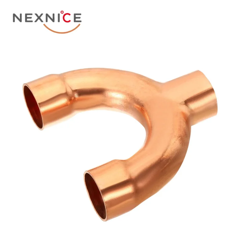
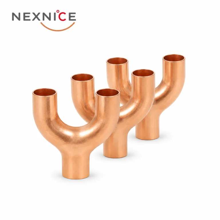
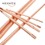
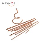
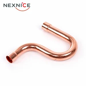
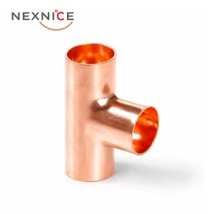
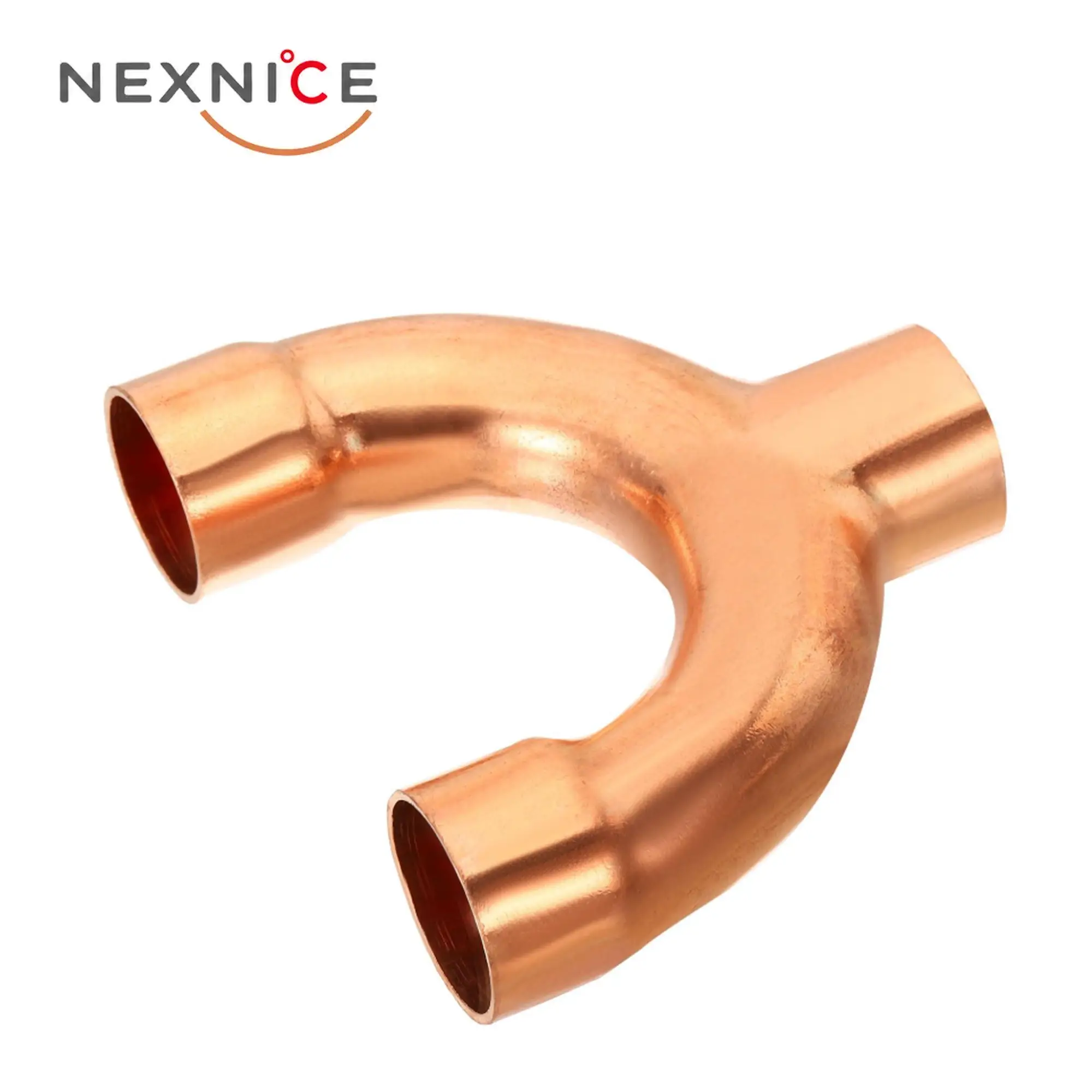
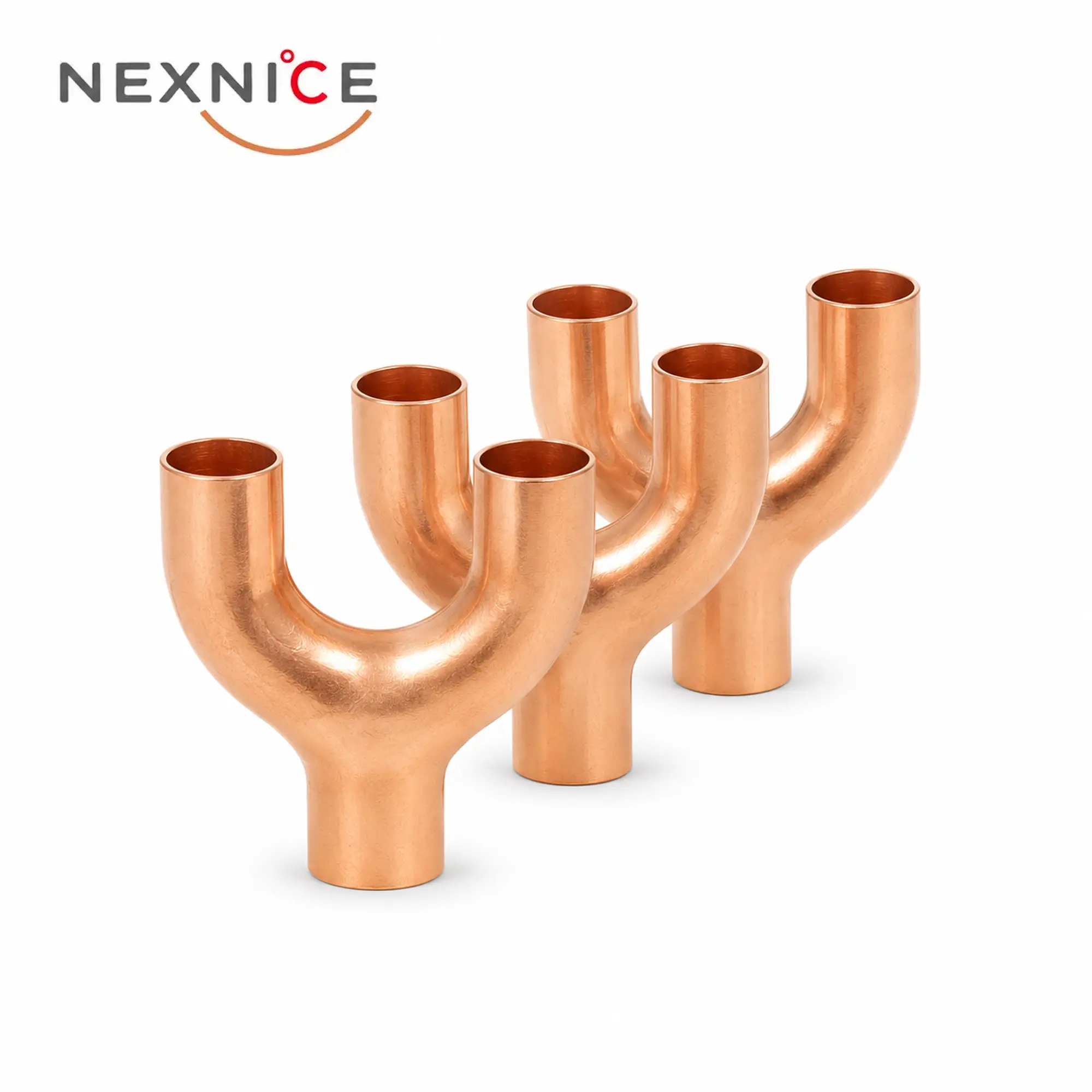
The fitting has one stem and two curved arms, each ending in a tube connection. This gives the pipework a three-way junction at the specified position in the assembly. For an equipment maker, the useful distinction is the branch layout: the component must align with three adjoining tube runs, including their spacing and direction.
Use the product name to identify the fitting family, then use a dimensioned drawing to identify the part. A catalogue size alone does not define the three-port arrangement or the overall space occupied by the curved body.
Construction and Connection Features
Three Connection Points in One Fitting
The common junction and two branch arms are contained in one fitting body. In the bill of materials, specify this as a Y-type copper fitting and identify each connection separately. This keeps the branch component distinct from the straight tubes and other bends used around it.
Curved Arms Define the Tube Approach
The illustrated arms curve away from the junction before reaching the end openings. Their shape makes branch-end spacing and straight-end length relevant to fit, especially when the adjoining tubes are held in a fixed fixture. Allow access around all three joints as well as clearance for the body itself.
Socket-Style Tube Ends
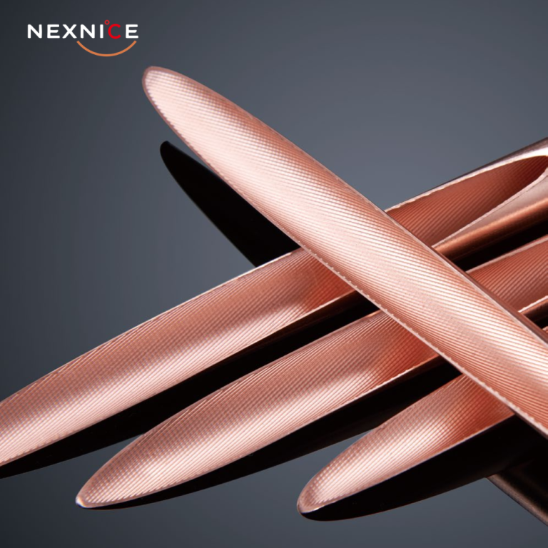
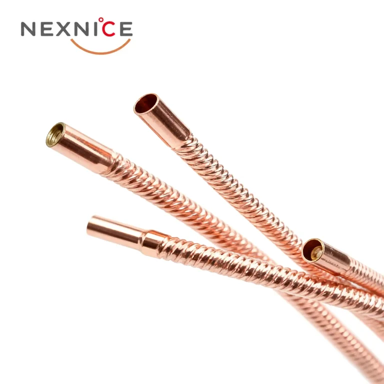
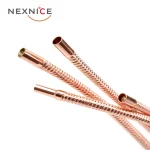
The supplied close-up shows open, expanded tube ends. For the joint detail, match the receiving end to the mating tube OD and specify insertion depth and the required joining procedure on the assembly drawing. Keep the tube-fit dimensions separate from the outside dimensions of the socket mouth.
Catalogue Size Range
The catalogue presents two size series. The inch entries below retain the millimetre references printed in parentheses in the source; those references include rounded values and are not manufacturing tolerances. The separate metric table lists the metric options in their original order.
Inch Size Series
| Catalogue size (in.) | Catalogue reference (mm) |
|---|---|
| 3/8 | 9.52 |
| 1/2 | 12.7 |
| 5/8 | 15.88 |
| 3/4 | 19.05 |
| 7/8 | 22.23 |
| 1 | 25.4 |
| 1-1/8 | 28.6 |
| 1-1/4 | 32 |
| 1-3/8 | 35 |
| 1-1/2 | 38 |
| 1-5/8 | 42 |
| 1-3/4 | 45 |
| 2-1/8 | 54 |
| 2-5/8 | 67 |
| 3 | 76 |
| 4-1/4 | 108 |
| 5-1/4 | 133 |
| 6-1/4 | 159 |
Metric Size Series
| Catalogue metric size (mm) |
|---|
| 10 |
| 12 |
| 15 |
| 16 |
| 22 |
| 25 |
| 28 |
| 32 |
| 35 |
| 38 |
| 42 |
| 45 |
| 54 |
| 67 |
| 76 |
| 108 |
| 133 |
| 159 |
These are independent size lists, not a row-by-row conversion chart. The size designation should be read together with the approved connection drawing for the ordered fitting.
How to Specify the Correct Fitting
Identify All Three Ports
Label the stem A and the two arms B and C on a sketch. For each port, state the mating tube OD, the inch or metric size system, and the receiving-end dimensions required by the joint design. Do not use a single size entry as a substitute for an A × B × C connection schedule.
Check Fit Using Dimensions, Not Table Position
For example, the inch list shows 3/4 in. with a 19.05 mm reference, while the metric series includes 16 mm. These are different size entries, even though they appear on the same row in the original catalogue. Use the mating tube specification to select the appropriate series.
Include the Dimensions That Locate the Tubes
Add branch-end spacing, end-axis directions, straight-end lengths and insertion depths to the drawing. Also show the available installation envelope. Two fittings described by the same tube size can still occupy different positions in a fixed assembly if these dimensions differ.
Choose a Branch or a Return According to the Route
A route that joins three tubes calls for a branch fitting. If the drawing instead connects two parallel tube sections through a 180-degree return, review the Copper Return Bend C × C and its centre spacing. The number of connections and the required tube route determine which fitting family to specify.