Single Coils and Paired Tubing
Single-Tube Coil
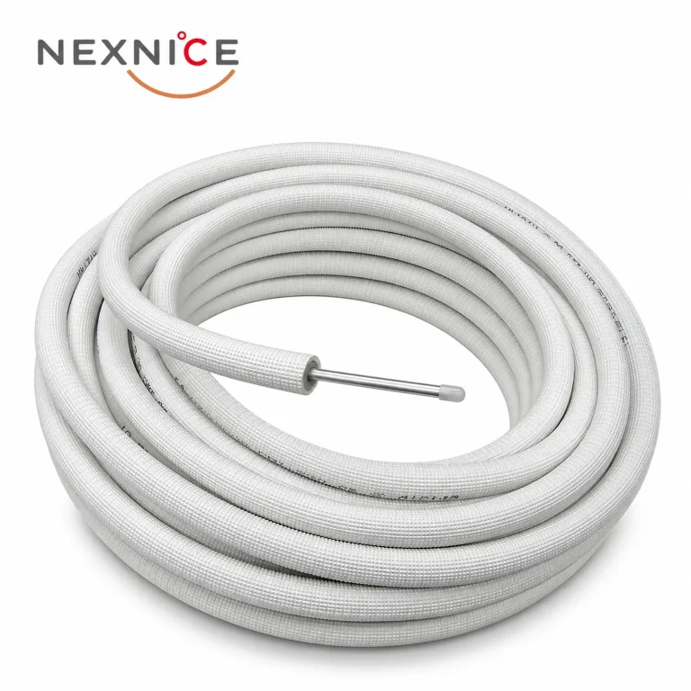
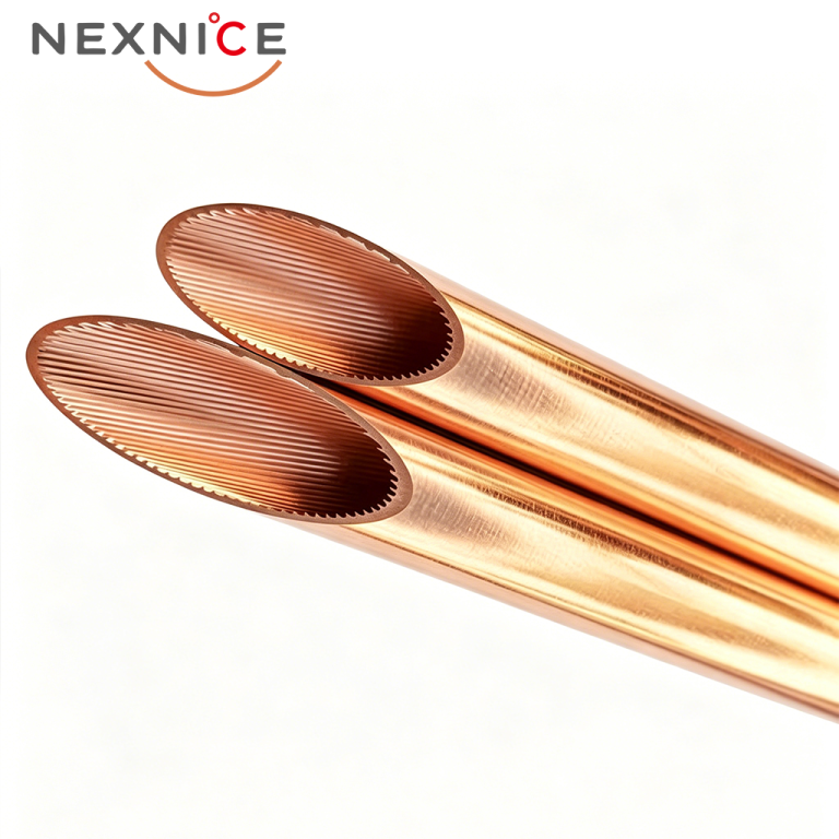
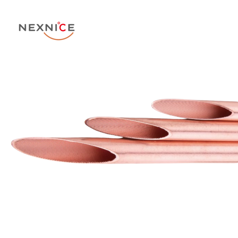
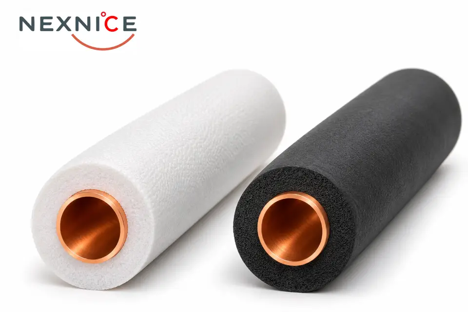
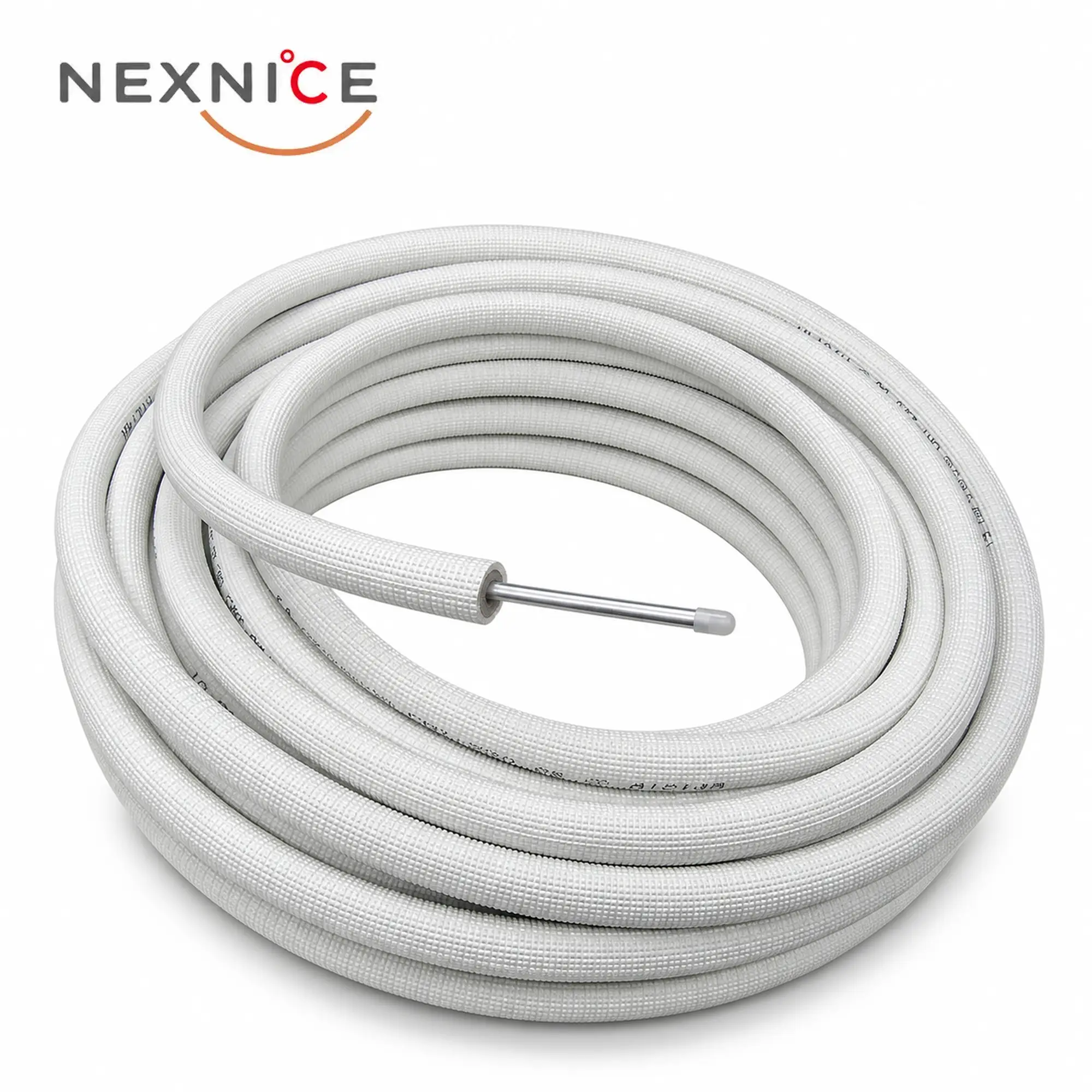
The single-coil format supplies one insulated tube size. It suits purchasing by individual pipe size, including orders where different diameters or lengths need to be stocked separately. The illustrated tube has an exposed metal end with a protective cap, leaving the connection arrangement to be specified for the intended assembly.
Paired Tubing with End Fittings
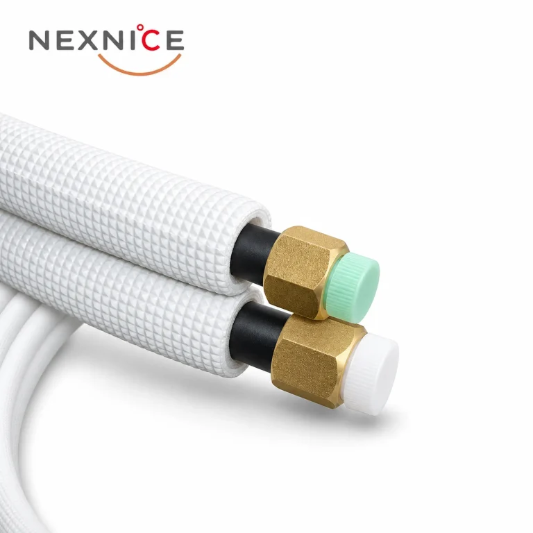
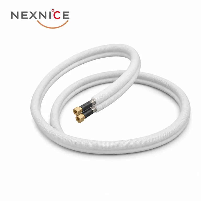
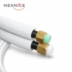
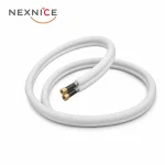
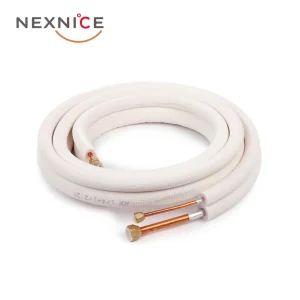
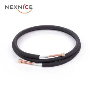
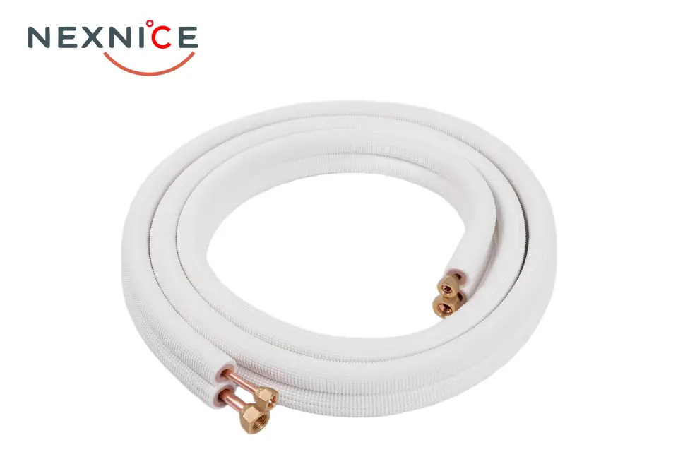
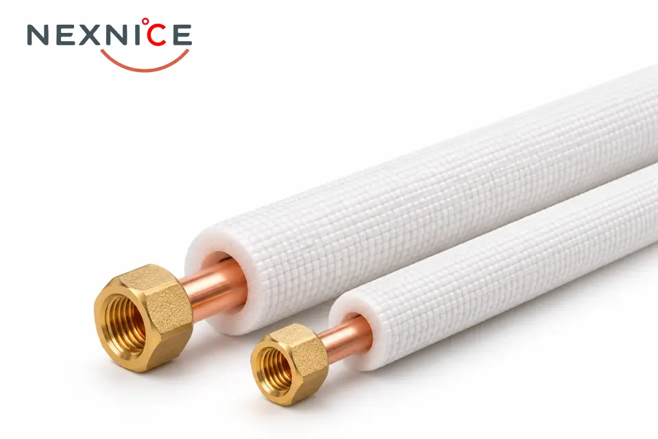
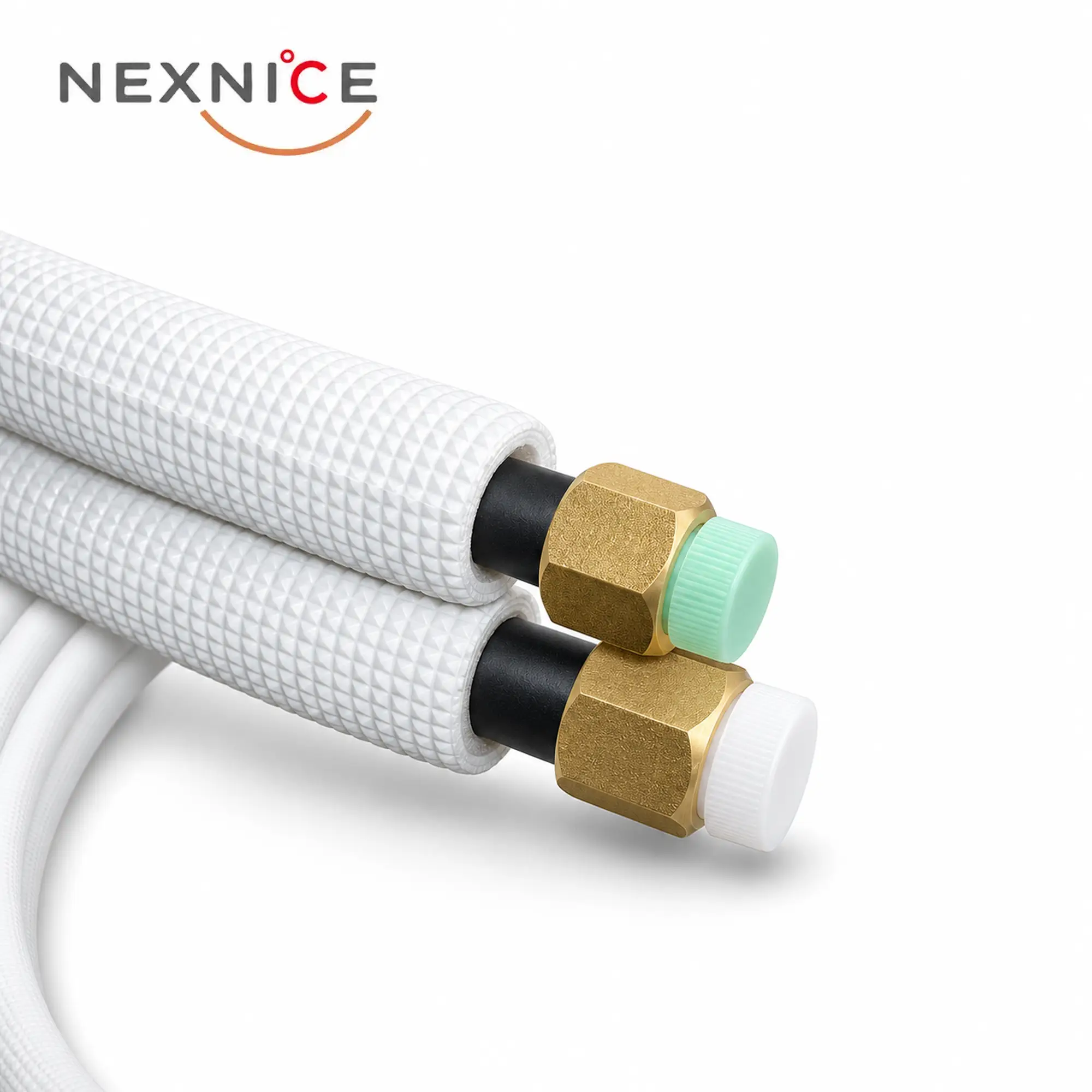
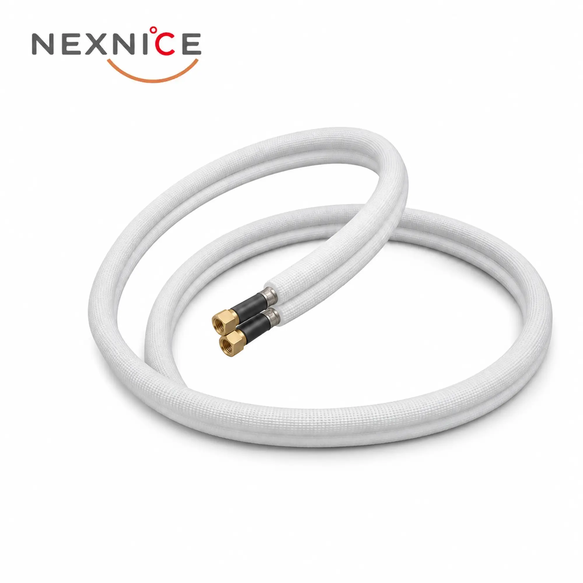
The paired format groups two insulated tubes for an equipment connection. The supplied photographs show nut-fitted ends and protective sleeves around the end sections. For this format, identify each tube separately: its outside diameter, wall thickness, insulation and length, followed by the required fitting details at each end.
A paired assembly is an ordering configuration, not a single tube size. The size table below lists individual tubes; it does not prescribe which two diameters must be paired.
Construction and Available Options
Aluminium Tube and Insulation Sized Separately
The metal tube is specified by outside diameter and wall thickness. The surrounding insulation has its own bore and thickness: the catalogue lists insulation thicknesses of 8, 9 and 10 mm across the range. Keeping these dimensions separate makes the purchase specification clear for both the fluid passage and the insulated assembly.
Fitted Insulation with a Textured Outer Surface
The illustrated product has white insulation with a textured outer surface. Supplying the tube already insulated removes the separate task of sleeving the main tube length. Connections and any site-cut sections still need insulation continuity appropriate to the installation.
Length, Insulation and End Preparation Options
Catalogue supply lengths are 1–50 m, with custom lengths accepted up to 50 m. Black rubber insulation can be requested. Nut-fitted ends are another listed option, allowing the end arrangement to be included in the order rather than assumed from a photograph.
Technical Specifications
The table lists individual aluminium tubes with their corresponding insulation dimensions. Dimensions are in millimetres unless stated otherwise.
| Tube size (in.) | Aluminium OD × wall (mm) | Insulation ID (mm) | Insulation thickness (mm) | Supply length (m) |
|---|---|---|---|---|
| 1/4 | 6.35 × 0.75 | 8 ± 0.5 | 8 | 1–50 |
| 3/8 | 9.52 × 0.8 | 12 ± 0.5 | 8 | 1–50 |
| 1/2 | 12.70 × 0.8 | 14 ± 0.5 | 8 | 1–50 |
| 5/8 | 15.88 × 1.0 | 18 ± 0.5 | 9 | 1–50 |
| 3/4 | 19.05 × 1.0 | 22 ± 1 | 9 | 1–50 |
| 7/8 | 22.22 × 1.2 | 25 ± 1 | 10 | 1–50 |
| 1 | 25.40 × 1.2 | 28 ± 1 | 10 | 1–50 |
| 1-1/8 | 28.58 × 1.2 | 32 ± 1 | 10 | 1–50 |
| 1-1/4 | 31.75 × 1.5 | 35 ± 1 | 10 | 1–50 |
| 1-1/2 | 38.10 × 1.5 | 42 ± 1 | 10 | 1–50 |
OD means outside diameter; ID means inside diameter. The tolerances shown in the insulation column apply to the insulation bore, not to the aluminium tube OD. Custom tube dimensions are subject to the agreed order specification.
How to Select and Specify
Read the Tube Wall and Insulation Thickness Correctly
For the 5/8 in. entry, the aluminium tube is 15.88 mm OD with a 1.0 mm wall. Its insulation is listed as 18 ± 0.5 mm ID with a 9 mm thickness. These are two separate components: 9 mm is the insulation thickness, and 18 mm is not the refrigerant passage diameter.
Define Both Tubes in a Pair
Specify tube A and tube B independently, then add the common assembly length if both are the same. State whether the ends are plain, flared or supplied with the required nut arrangement, using the equipment drawing to define the mating connection. A nut appearance or cap colour does not identify its thread or sealing geometry.
Match the Material to the Equipment Requirement
An aluminium tube and a copper tube with the same nominal size are not automatically interchangeable. Where the project specifies paired copper tubing, review Insulated Copper Pair Coil as the relevant product family. Keep the required material, wall thickness and connection method together when comparing quotations.
Choose Length for the Route and Supply Format
Order the length needed for the planned route and the assembly allowance specified for the job. The 50 m catalogue maximum describes the available supply length; it does not mean every air conditioner permits a 50 m connecting line. For single coils intended for cutting into several pieces, state the coil length separately from the finished piece length.